Table of Contents
Advertisement
Quick Links
Advertisement
Table of Contents

Related Manuals for ABL eMS home


Summary of Contents for ABL eMS home
- Page 1 Energy Management System eMS home User manual Article No.: 0301675_EN_a...
-
Page 2: Contact
Contact Contact ABL GmbH Albert-Büttner-Straße 11 91207 Lauf an der Pegnitz Germany +49 (0) 9123 188-0 +49 (0) 9123 188-188 info@abl.de www.ablmobility.de Customer Service +49 (0) 9123 188-0 service@abl.de www.ablmobility.de/de/service/support/ Revision: 0301675_EN_a, Version: 21.01.22... -
Page 3: Table Of Contents
Bus wiring of the wallboxes and the eMS home Termination of the data lines Setting up the wallboxes Cable connection with the computer Configuration via the ABL Configuration Software Starting up the eMS home Starting the eMS home web interface Structure of the web interface Checking and updating the device firmware Setup via the eMS home web interface... - Page 4 Contents...
-
Page 5: Additional Technical Information
Energy Management System home. This is available in separate documents. The technical data for the Energy Management System home and the eMH1 Wallboxes are also summarised concise- ly in product-specific data sheets. You can download these documents from the ABL website using the following link: https://www.ablmobility.de/en/service/downloads.php... -
Page 6: Introduction
Introduction – General Introduction General This manual describes all working steps required to install and/or operate the product it concerns. Certain sections of this manual are specially formatted for quick and easy reference. ► Descriptions of completed actions are marked with a triangle. ƒ... -
Page 7: Identification Of The Ems Home
However, it does not show any access data for communication between the integrated web server of the eMS home and a computer. Verpackungsschild H:\_Key Acoount\ABL\Branding\ABL_Etiketten mit Anpassungen_18Nov2021.docx / 23.11.21 / Ober, Claudia Seite 1 von 1... -
Page 8: Connections And Controls
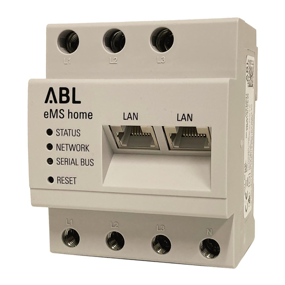
Introduction – Connections and controls Connections and controls Number Designation Outer conductor L1, L2, L3 outputs RS485 A connection RS485 B connection 2 × LAN connection Neutral conductor N Outer conductor L1, L2, L3 inputs Reset button Serial bus LED for RS485 bus Network LED Status LED... -
Page 9: Rs485 Interfaces
Introduction – RS485 interfaces RS485 interfaces There are two RS485 interfaces on the top of the eMS home ( ) which are used for communication with the eMH1 Wallboxes. The following specifications apply to the RS485 interfaces: Requirement for the data cable ƒ... -
Page 10: System Installation
System installation – Phase rotation System installation The Energy Management System eMS home can be used to control up to six eMH1 Wallboxes. Detailed information on how to install the eMH1 Wallbox can be found in the corresponding installation instructions. These are available at: https://www.ablmobility.de/en/service/downloads.php Phase rotation For the system to function correctly, the phase rotation must be set up according to the following diagram when... -
Page 11: Electrical Connection Of The Ems Home For Direct Measurement Without Current Transformer
Proceed as follows: Mount the eMS home on a top-hat rail. Consumer y Hook the eMS home onto the top edge of the top-hat rail and press it until it clicks into place. eMS home eMS home as STATUS a grid supply and NETWORK Connect the conductors to the eMS home. -
Page 12: Electrical Connection Of The Ems Home For Indirect Measurement With Current Transformers
DANGER: see tions” on page 48). note below Connect the connecting cables for the voltage meas- urement to the eMS home (see also box below). Circuit breaker y Pay attention to the permissible tightening torque for the screw terminals (see “Technical specifica- tions”... -
Page 13: Bus Wiring Of The Wallboxes And The Ems Home
Important note on plugging in the RS485 connector in the eMS home Please note that the RS485 connector may only be plugged into the eMS home after configuration in the ABL Configuration Software (see page 17 onwards): Otherwise, there may be problems with communication in the system. - Page 14 System installation – Bus wiring of the wallboxes and the eMS home ƒ The colour assignment between the data lines and the contacts evcc/rfid A, evcc/rfid B and evcc/rfid M on the spring terminals must be identical in every wallbox in the system and must not be changed under any circumstances.
-
Page 15: Termination Of The Data Lines
Service > All downloads > Software > Configuration Soft- ware. To do this, after completing the mechanical and electrical installation of the wallboxes, establish a data con- nection between the computer on which the ABL Configuration Software is installed and the bus interface of the wallboxes. -
Page 16: Cable Connection With The Computer
System installation – Cable connection with the computer Cable connection with the computer To connect the Wallbox eMH1 to a Windows PC, you will need the configuration kit CONFCAB (separately available accessory), which makes the wallbox's Modbus interfaces compatible with the computer's USB port. Using CONFCAB components, any charging station from the Wallbox eMH1 product series can be connected by cable: USB extension cable ƒ... -
Page 17: Configuration Via The Abl Configuration Software
System installation – Configuration via the ABL Configuration Software Wallbox eMH1 with E2I interface (from mid-2021) Remove the upper part of the housing. y This procedure is described in the section “Prepar- ing and mounting the wallbox” in the installation instructions for the eMH1 Wallbox. - Page 18 After addressing all charging stations, set the RCDs of all charging stations to position I. After completing the configuration, you can exit the ABL Configuration Software and disconnect the data cabling with the computer via the CONFCAB cable.
-
Page 19: Starting Up The Ems Home
After addressing and setting up the wallboxes, you can complete the wiring of the data cables between the eMS home and the wallboxes by inserting the RS485 connector in the eMS home and then starting up the eMS home via a PC/laptop. -
Page 20: Starting The Ems Home Web Interface
System installation – Starting the eMS home web interface Connect the other end of the network cable (directly or via a router/switch) to a PC/laptop. Reconnect the house connection to the mains. y The LEDs on the eMS home will light up during start-up. -
Page 21: Structure Of The Web Interface
System installation – Structure of the web interface ► In the login window, enter the factory-assigned password to log in to the eMS home. You will find the password on the rating plate attached to the side of the eMS home or the rating plate included in the package (see page 7). -
Page 22: Checking And Updating The Device Firmware
System installation – Checking and updating the device firmware NOTE Shortcut button for navigation You can return directly to the dashboard at any time by clicking on the ABL button in the top right corner of the web application. Checking and updating the device firmware For proper operation, it is recommended to check the internal software (firmware) of the eMS home at regular inter- vals and update it if necessary. -
Page 23: Setup Via The Ems Home Web Interface
System installation – Setup via the eMS home web interface Click the Browse button in the Update device firm- ware section in the lower part of the widget. y Enter the path for the file downloaded in step 4 and confirm your entry with OK. Click the UPDATE button to transfer the firmware to the eMS home. - Page 24 Adding additional wallboxes as charging devices Repeat steps 7 to 9 for each additional wallbox you want to add to the system. ƒ Make sure the Wallbox ID (address number from the ABL Configuration Software) is assigned consecu- tively. Otherwise, faultless communication cannot be guaranteed.
- Page 25 System installation – Setup via the eMS home web interface Use this method to add all wallboxes (up to a maxi- mum of six): If they are shown with a green tick in the Status column, communication with the eMS home is set up correctly.
-
Page 26: Description Of The Individual Apps Of The Ems Home
Description of the individual apps of the eMS home – Dashboard Description of the individual apps of the eMS home The dashboard of the eMS home web interface (see below) provides basic information about the system and allows access to individual apps at any time. These are described in more detail in the following sections. Dashboard The dashboard contains the Energy balance 1 and Phase values 2 widgets. -
Page 27: Messages - Health Check App
Description of the individual apps of the eMS home – Messages – Health Check app Messages – Health Check app Description The Health Check app centrally manages Messages 1that are sent from the apps to the user. If there are any un- read messages, the number of unread messages appears in red on the bell icon. - Page 28 Description of the individual apps of the eMS home – Messages – Health Check app Settings The settings for configuring the Health Check app can be opened by clicking the button with the gear icon 6. Email export can be enabled (Enable email export 1) once the email settings have been configured in the Device settings (see chapter “Device settings app”...
-
Page 29: Smart Meter App
Description of the individual apps of the eMS home – Smart Meter app Smart Meter app The line diagram shown in the Active power 1 widget shows a short-term trend of the total active power over the three individual phases. The power values displayed in the app are marked with a (+) when drawing power and a (-) when feeding in power. -
Page 30: Wallbox App
Description of the individual apps of the eMS home – Wallbox app Wallbox app The Wallbox app displays the current status of all connected charging devices. For each charging device, a graphic is displayed to visualise the status, including a pause button. The name of the charging device and an info button i, which opens a detailed view, are displayed above it. - Page 31 Description of the individual apps of the eMS home – Wallbox app Detailed view For each connected charging device, a detailed view can be opened by clicking on the info button i. There are three sections here: The status of the charging device is specified here in text form. Status The measured values for the current charging process are displayed here: Current charging process...
- Page 32 Description of the individual apps of the eMS home – Wallbox app ƒ If Charging with surplus PV is selected, the vehicle is only charged when electricity produced in the house itself – typically photovoltaic electricity – is available, which would otherwise be fed into the grid. This mode can be used to increase the self-consumption of the electricity produced.
- Page 33 Label, Type or Address. The configured name of the charging device is displayed here. Label The type (ABL charging device) is displayed here. Type The configured Wallbox ID of the charging device is displayed here.
- Page 34 Adding an ABL charging device The dialogue for adding an ABL charging device contains an input field for a name of your choice (1-20 characters), a menu for selecting the Modbus interface (RS485 A or RS485 B) and an input field for the Wallbox ID of the charging device (1-6).
-
Page 35: Data Store App
Description of the individual apps of the eMS home – Data store app WARNING! Correctly specifying the rated currents Correctly specifying the rated currents is essential for the overload protection to function properly. If the set val- ues are less than the actual value of the fuse, charging cannot be carried out with the maximum available cur- rent. - Page 36 Description of the individual apps of the eMS home – Data store app Energy data The Energy data widget displays a selection of energy values for consumption and feed-in with the corresponding OBIS code on a daily basis. Data source The following Data sources 1 are available for selection: ƒ...
- Page 37 Description of the individual apps of the eMS home – Data store app Manual data export The Manual data export widget allows the saved data of the eMS home, including the values for the sensors, to be exported from the database to a CSV file. The time Resolution 3 of the exported values is determined by the selected time period, which is defined with the fields From 1 and To 2, based on the following specifications: Selected period...
- Page 38 Description of the individual apps of the eMS home – Data store app Export settings The Export settings widget can be used to configure the automatic export of stored energy values in CSV format. Schedule In the Schedule section, you can select the Transmission interval 2 and the Resolution 3 of the exported file. The resolution can be selected depending on the selected send interval: Transmission interval Choice of resolution...
-
Page 39: Device Settings App
Description of the individual apps of the eMS home – Device settings app Email export settings Email export can be enabled (Enable email export ) once the Email settings have been configured in the Device settings (see chapter “Device settings app” on page 39). The Email address of the recipient 9 is displayed at this point for information only. - Page 40 Description of the individual apps of the eMS home – Device settings app System info This widget contains general system information and information about the current status of the eMS home. The fol- lowing details are displayed: ƒ Product name ƒ Installed firmware version ƒ...
- Page 41 Description of the individual apps of the eMS home – Device settings app Network settings The Network settings widget provides access to all the configuration settings required to integrate the eMS home into the local network. The Host name 1 is the unique name of the eMS home in the network. It can be freely selected and can contain upper-case and lower-case letters, numbers and hyphens.
- Page 42 Description of the individual apps of the eMS home – Device settings app FTP settings In this widget, settings for using FTP can be changed. The following configuration fields are shown 1: ƒ Protocol: Choice between FTP and SFTP, activation of Passive mode ƒ...
- Page 43 Description of the individual apps of the eMS home – Device settings app Email settings In this widget, settings for sending emails can be changed. The following configuration fields are shown 1: ƒ Email address: Email recipient ƒ SMTP server: SMTP server that sends the emails ƒ...
- Page 44 Description of the individual apps of the eMS home – Device settings app Support for other providers may vary. Please contact your provider for information on how to connect the eMS home. Whether or not authentication is required for connection to the company’s own email server depends on the configuration.
- Page 45 Description of the individual apps of the eMS home – Device settings app Backup Create a backup Clicking CREATE 1 opens a widget that can be used to create a backup of the system settings and collected data. You have the option to enter a password in the Password field to protect the data backup. Please note the following information in the widget: WARNING: The system does not perform any measurements while the backup is being cre- ated.
- Page 46 Description of the individual apps of the eMS home – Device settings app Device General settings can be changed in this widget. Date and time 1 It is important to always set the Time zone so that factors such as date limits or summer/winter time in the local time zone are correctly taken into account by the system.
- Page 47 Description of the individual apps of the eMS home – Device settings app interface” on page 20). The factory password can be read from the rating plate label attached to the side of the de- vice as well as the separate rating plate label included in the package. Update device firmware 4 A new device firmware can be installed in this area.
-
Page 48: Appendix
Appendix – Technical specifications Appendix Technical specifications General 2 × LAN (10/100 Mbit) Interfaces 2 × RS485 (half-duplex, max. 115.200 baud) Class of protection IP rating IP2X 10 – 25 mm² * Connection cross section in line with EN 60204 *Mechanical: 1.5–25 mm² (e.g. for connecting external cur- rent transformers) Tightening torque for screw terminals 2.0 Nm Weight... -
Page 49: Operation Of The Ems Home At An Ambient Temperature Of 55 °C
ƒ The length of the data lines within the group installation must not exceed 100 m. PIN allocation within the system eMH1 with spring terminal eMS home eMH1 with RJ45 connector Conductor colour* Top view of ABL bus RS485 Top view PIN allocation Twisted pair terminal allocation... -
Page 50: Functions Of The Reset Button
This product also contains open source software that was developed by third parties. This includes the GPL and LGPL licenses. The licence texts containing the associated information can be found on the eMS home web interface in the footer under Licenses. -
Page 51: Abbreviations
Appendix – Abbreviations Abbreviations Abbreviation Description Comma-Separated Values Energy Manager File Transfer Protocol General Public License LGPL Lesser General Public License JSON JavaScript Object Notation MQTT Message Queuing Telemetry Transport Photovoltaics SFTP Secure File Transfer Protocol SMTP Simple Mail Transfer Protocol UPnP Universal Plug and Play Error codes... - Page 52 Appendix – Error codes Error code Error description and remedy The password you entered or the backup file you submitted is not valid. Please check the file used and the associated password. If this data is not available, please create a new backup file and password and repeat the process. The firmware upgrade could not be performed.
-
Page 53: Obis System Of Indicators
Appendix – OBIS system of indicators Error code Error description and remedy The CSV file could not be exported via FTP/SFTP. Please check the FTP/SFTP configuration in the eMS home and the configuration of the FTP/SFTP server. ƒ If the error persists, please create the system logs and contact Customer Service or the FTP provider. -
Page 54: Data Storage App - Csv Export Format
Appendix – Data Storage app – CSV export format Group E (tariff level) Key value of the tariff, usually E = 0 (total) Group F (previous value meter reading) F = 255 Please note: The values of groups A and F are fixed, those of the remaining groups are variable. Data Storage app –... - Page 55 Appendix – Data Storage app – CSV export format Description OBIS code Unit Apparent energy- 1-0:10.8.0*255 Power factor 1-0:13.4.0*255 none Power factor min 1-0:13.3.0*255 none Power factor max 1-0:13.6.0*255 none Supply frequency 1-0:14.4.0*255 Supply frequency min 1-0:14.3.0*255 Supply frequency max 1-0:14.6.0*255 Active power+ (L1) 1-0:21.4.0*255...
- Page 56 Appendix – Data Storage app – CSV export format Description OBIS code Unit Voltage (L1) min 1-0:32.3.0*255 Voltage (L1) max 1-0:32.6.0*255 Power factor (L1) 1-0:33.4.0*255 none Power factor (L1) min 1-0:33.3.0*255 none Power factor (L1) max 1-0:33.6.0*255 none Active power+ (L2) 1-0:41.4.0*255 Active power+ (L2) min 1-0:41.3.0*255...
- Page 57 Appendix – Data Storage app – CSV export format Description OBIS code Unit Power factor (L2) 1-0:53.4.0*255 none Power factor (L2) min 1-0:53.3.0*255 none Power factor (L2) max 1-0:53.6.0*255 none Active power+ (L3) 1-0:61.4.0*255 Active power+ (L3) min 1-0:61.3.0*255 Active power+ (L3) max 1-0:61.6.0*255 Active energy+ (L3) 1-0:61.8.0*255...
-
Page 58: Faqs - Frequently Asked Questions
Problems during configuration with the ABL Configuration Software ƒ Make sure that the RS485 connector on the eMS home is disconnected when configuring the wallboxes. ƒ Please refer to the section "Troubleshooting" in the manual of the ABL Configuration Software (→ ABL Con- figuration Software). -
Page 59: Disposal Notice
Appendix – Disposal notice Disposal notice The crossed out trash can symbol indicates that electrical and electronic devices including acces- sories must be disposed of separately from household waste. The materials are recyclable as marked. The reuse or recycling of materials, or other forms of repurposing of old devices make an important contribution towards protecting the environment. - Page 60 ABL GmbH Albert-Büttner-Straße 11 91207 Lauf an der Pegnitz Germany +49 (0) 9123 188-0 +49 (0) 9123 188-188 info@abl.de www.ablmobility.de...
Need help?
Do you have a question about the eMS home and is the answer not in the manual?
Questions and answers