
Related Manuals for Eventide DIR911t


Summary of Contents for Eventide DIR911t
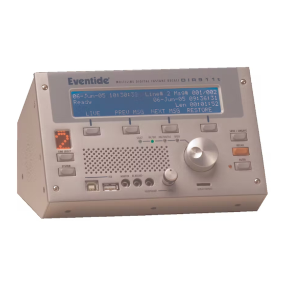
- Page 1 DIR911t User Guide Versions 1.8.3 2005, 2006, 2007, 2008 Eventide Inc. For manual and software updates please visit www.eventide.com...
-
Page 3: Via The Internet
Safety Precautions After unpacking the DIR911t, save all packing materials in case you ever need to ship the unit. Thoroughly inspect the DIR911t and packing materials for signs of damage. Report any shipment damage to the carrier at once;... -
Page 4: Compliance Information
The telephone company will provide advance notice of any such changes so that you can make the necessary modifications to maintain uninterrupted service. If you experience trouble with this device, contact Eventide for warranty or repair information: Eventide Inc. -
Page 5: United States Fcc Part 15 Compliance Statement
United States FCC Part 15 Compliance Statement This device complies with the United States’ CFR 47 Part 15 (FCC Part 15). Specifically: • FCC Part 15, Subpart B, Section 15.107(a) and Section 15.109(a), Class A Digital Device. Operation is subject to the following two conditions: •... -
Page 6: Warranty Information
Who is covered under this warranty The warranty applies to the original purchaser of a new unit from Eventide or an authorized Eventide dealer. Demo units are also covered by this warranty under slightly different circumstances (see below). -
Page 7: When The Warranty Becomes Effective
The one-year warranty period begins on the day the unit is purchased from an Authorized Eventide Dealer or, if the unit is drop-shipped from Eventide, on the day shipped, plus a reasonable allowance for shipping delays. This applies whether or not you return your warranty registration form. -
Page 8: Shipping From Outside The United States Or Canada
We will return the unit to you prepaid, at our expense, using an expeditious shipping method, normally United Parcel Service or Federal Express. In areas not served by UPS or Federal Express we will ship by US Mail. If you are in a hurry and want us to use a premium shipping method (such as air express, next day air, etc.), be sure you tell us and agree to pay shipping charges. -
Page 9: Table Of Contents
Table of Contents Contacting Eventide......................3 via United States Mail....................3 via the Internet ......................3 via Telephone......................3 via Facsimile ....................... 3 via Email ........................3 Safety Precautions......................3 Compliance Information ....................4 United States FCC Part 68 Telecommunications Statement........4 United States FCC Part 15 Compliance Statement............. - Page 10 Recall Mode ........................37 Emailing Messages from Recall Mode ..............38 System Mode ........................ 38 Save to USB Drive....................40 Save to USB Drive by Call Number ..............41 Save to USB Drive by Date Range ............... 41 Save to USB Drive by Call Filter ................. 42 Set Autorestore Time ....................
- Page 11 Email Server Setup ....................59 Security Level ......................60 Password Setup ......................60 Add-On License Key ....................61 Add User ........................61 Delete User........................ 62 Configure Line Name ....................62 Split Mode......................... 63 Import/Export System Configuration ............... 63 Firmware Upgrade ....................64 Raid Status ........................
- Page 12 Headphone Output Connector................... 82 Rear Panel ........................83 Power Input Connector ..................... 85 Telephone Line Connectors ..................86 Auxiliary Input Connectors..................87 ALI Input Connector....................87 ANI Input Connector ....................88 External Activity Connector ..................89 Time Sync Input / Console Connector..............91 USB A “Host Side”...
- Page 13 Table of Figures Figure 1: Front Panel Diagram ..................23 Figure 2: Rear Panel Diagram..................27 Figure 3: Power Up Screen ....................32 Figure 4: Boot Screen ...................... 33 Figure 5: Main Screen...................... 33 Figure 6: Main Screen...................... 35 Figure 7: Recall Screen ....................37 Figure 8: Recall Email Screen ..................
- Page 14 Figure 28: Off Hook Activation Level Screen..............51 Figure 29: Test External Closure Screen ................. 51 Figure 30: Audible Beep Level Screen................52 Figure 31: ALI/ANI Setup Screen ................... 52 Figure 32: Configure ALI/ANI Serial Ports Screen ............54 Figure 33: Centralized Archive Setup Screen..............54 Figure 34: Centralized Archive Pointer Setup Screen .............
- Page 15 Figure 56: Incoming Line Filter Screen................70 Figure 57: DTMF Digits Filter Screen................71 Figure 58: Caller ID Digits Filter Screen................. 71 Figure 59: Front Panel Connector Locations ..............78 Figure 60: Front Panel USB A Connector Pin Diagram..........79 Figure 61: Front Panel USB B Connector Pin Diagram ..........
- Page 17 Table of Tables Table 1: Front Panel Legend.................... 26 Table 2: Rear Panel Legend..................... 30 Table 3: Status Field Descriptions ................... 36 Table 4: Compression Methods ..................47 Table 5: Line Activation Methods ................... 48 Table 6: Line Activation Methods ................... 49 Table 7: Clock Synchronization Methods................
-
Page 19: Introduction
• Re-Record output. A re-record output is available and can be used to record as the unit is playing back. • Multiple line capability. The DIR911t can independently monitor and record up to 4 telephone lines or 4 line level input sources depending on the configuration purchased. -
Page 20: Front Panel
The front panel of the DIR911t has been designed for simplicity, elegance, and above all ease of use. The controls and ports of the DIR911t front panel is shown in Figure #1. Further, if you have used the previous Eventide model DIR911 you will immediately be... -
Page 21: Figure 1: Front Panel Diagram
DIR911T User Guide Figure 1: Front Panel Diagram... - Page 22 LINE DISPLAY: The 5 by 7 LED array displays the currently active line. When in system mode, the display flashes ‘S’ LCD SCREEN: The DIR911t contains a 40 by 4 character LCD display used to present information to the user. LCD contrast may be...
- Page 23 LEVEL: This knob is used to adjust the volume of the speakers (or the headphones if they are currently in use) HEADPHONE JACK: The DIR911t supports a single set of stereo headphones via this 3.5mm stereo phono jack. When headphones are plugged into the unit, the speakers are muted.
-
Page 24: Rear Panel
DIR911T User Guide USB A: The DIR911t provides a single USB-A “host” connector. This may be used to connect USB peripherals such as USB storage keys to the unit. USB B: The DIR911t provides a single USB-B “peripheral” connector. This is used for connecting a laptop or similar system to the DIR911t for field service by an authorized Eventide technician. -
Page 25: Figure 2: Rear Panel Diagram
DIR911T User Guide Figure 2: Rear Panel Diagram... - Page 26 DIR911T User Guide Each of the controls and ports is described in the Table #2 below. NOTE: A later chapter completely describes the pin numbering and pin function of each port on the front panel. Each of the ports is described below.
- Page 27 ETHERNET PORT: The DIR911t provides a single 10/100Mbps Ethernet LAN connection. USB A: The DIR911t provides two USB-A “host” connectors on the rear panel. These may be used to connect USB peripherals such as USB storage keys to the unit.
-
Page 28: Table 2: Rear Panel Legend
DIR911T User Guide chassis ground for the unit. EXPANSION BRACKET: If a four-channel unit is purchased, this is where the connectors for the second set of lines are provided. The line connections are identical to items G-J above. TIME: This connector is where an external GPS receiver is connected to the unit. -
Page 29: Installation
Each line of the DIR911t has two female RJ-11 jacks that are used to connect the unit to the telephone line. Plug the telephone line into one of the two jacks (they are the same so it doesn’t matter which). -
Page 30: Figure 3: Power Up Screen
DIR911T User Guide 4. ALI/ANI Connection. If out of band ALI/ANI sources are to be used with the unit, plug them into the appropriate DB-9 connector on the rear panel. The pinout of the ALI connector is given in Table #17. The pinout of the ANI connector is given in Table #18. -
Page 31: Powering Down The Unit
DIR911T User Guide Eventide Model DIR911t Multi-Line Install Recall Recorder Version: 1.8.0[3] Figure 4: Boot Screen 8. After the unit boots and runs its internal startup tests, it will display the main screen. This is shown in Figure #5. 16-May-68 04:31:12... -
Page 33: Operation
DIR911T User Guide Operation The DIR911t always operates in one of three modes: MAIN, RECALL, and SYSTEM. The main mode is where the unit spends most of its time and is the mode in which the unit enters upon power-up and when the system or recall modes are exited. -
Page 34: Table 3: Status Field Descriptions
DIR911T User Guide • The current line selected is shown on the 5x7 LED matrix. • The current call number and total message count are shown in the upper right hand corner of the screen. • Directly below the date and time is the current status of the unit. The status field... -
Page 35: Recall Mode
DIR911T User Guide The LIVE soft key will enable live monitoring of the currently selected line on the Speaker/Re-Record output. Pressing the LINE soft key again will disable this. When live monitoring, the ‘*’ character will be displayed to the left of the LINE soft key label. -
Page 36: Emailing Messages From Recall Mode
DIR911T User Guide The KNOB may also be used to maneuver around the call. Pressing the KNOB will pause the call. While paused, turning the KNOB will rewind and fast forward through the call. Press the KNOB again to continue playing. -
Page 37: Save To Usb Drive
If this is the case, the user will be placed directly in the system screen. NOTE: the factory default setting for the DIR911t is in high security mode with a default password of: 0000. This means on initial configuration you can simply press the DONE soft key. -
Page 38: Save To Usb Drive By Call Number
DONE Figure 12: Save Call to USB Drive Screen The DIR911t is able to save calls recorded and stored internally to an external USB mass storage devices (commonly called USB keys or USB flash drives). This screen is used to select the type of save to perform. -
Page 39: Save To Usb Drive By Date Range
DIR911T User Guide Save to USB Drive by Date Range The save calls to USB by call number screen is shown in Figure #14. Include calls that start between: 08-NOV-07 15:45:30 and: 09-NOV-07 15:45:30 CURSOR SAVE DONE Figure 14: Save Call to USB Drive By Date Range Screen Use the “CURSOR”... -
Page 40: Set Autorestore Time
Use the encoder to adjust the autorestore time. Press the DONE key to exit the menu. Line Auto Jump Setup The Line Auto Jump feature allows the DIR911t to switch to the line with the most recent call that is being recorded. The screen is shown in Figure #17. -
Page 41: Call Filter Use Setup
Call Filter Use Setup The Call Filter Use feature allows the DIR911t administrator to deny the use of the call filter to non-administrator users. When the call filter is disabled, pushing the FILTER key will show a screen that indicates that the call filter is disabled and to contact the administrator for information. -
Page 42: Automatic Gain Control Setup
This setting is used to boost or attenuate the telephone or AUX input level before being digitized by the DIR911t. The current line signal level is shown for convenience. Use the encoder to select the gain value. Press the CURSOR soft key to move between the Telephone and Auxiliary gain. -
Page 43: Sampling And Compression
DIR911T User Guide Monitor output gain: -0.0dB Re-Record out. gain: -0.0dB DONE Figure 22: Monitor and Re-Record Output Level Adjust Screen The Monitor and Re-Record output screen allows for adjusting the output gain for the respective output. This is true analog gain in that it is applied after the D/A conversion process. -
Page 44: Recording Priority
DIR911T User Guide Method Description PCM Linear Data is recorded as 16-bit linear PCM samples. This option provides the best fidelity but also consumes the most space. A-Law This option records the samples as A-law encoded values. This provides a 2 to 1 compression ratio. -
Page 45: Recording Activation
ENABLE ENABLE DISABLE DISABLE CURSOR DONE Figure 25: Record Activation Screen These settings are used by the DIR911t to decide when it should start recording the selected line. One or more of the following methods may activate each line:... -
Page 46: Vox Record Activation Threshold
Figure 26: VOX Record Activation Threshold Screen This setting is used by the DIR911t to decide if there is enough voice activity on the telephone or auxiliary line to start recording. If at any time the voice level on the telephone line is above this value and the “line”... -
Page 47: Set Vox Hold Time
Figure 28: Off Hook Activation Level Screen This setting is used by the DIR911t to decide if the line voltage is low enough to constitute an off hook condition. If at any time the line voltage is below this threshold... -
Page 48: Test External Relay Closure Activation
DIR911T User Guide and the HOOK setting in the line activation mechanism screen is enabled the DIR911t will activate the line and start recording. For convenience, the voltage for the current line (as well as its current state) is shown. -
Page 49: Ali/Ani Setup
Automatic Number Information (ANI), and Automatic Location Information (ALI). When set to Internal (CID), circuitry in the DIR911t uses Caller ID to extract the ANI information and presents it on the screen. When set to out of band, circuitry external to the DIR911t is responsible for recovering the ANI information and sending it to the unit via the ANI serial ports. -
Page 50: Configure Ali/Ani Serial Ports
NPA-XXX-XXXX CF # NPA-XXX-XXXX If the ALI data received by the DIR911t are in the above from, you would set the line number to 2 for the 2 line, you would set the column number to 1 for the 1... -
Page 51: Centralized Archiving Setup
This screen is used to set the BAUD rate of the ALI and ANI serial ports. The values supported by the DIR911t are 9600, 4800, 2400, 1200, and 300. Use the encoder to select the appropriate BAUD rate. Use the CURSOR soft key to select the ALI or ANI serial port. -
Page 52: Centralized Archive Pointer Setup
Turn the encoder to the desired value. Press the DONE soft key to update the pointer and exit this menu. NOTE: updating the archive pointer may take some time depending on the DIR911t model number and the number of calls currently stored. -
Page 53: Date/Time Setup
This screen is used to set the unit’s time and date. There are many sources to which the DIR911t can synchronize its internal clock. These include its internal battery backed hardware clock, Network Time Protocol (NTP) servers, and NMEA GPS serial streams,... -
Page 54: Ethernet Setup
DIR911T User Guide Method Description Date/Time information is recovered from the internal hardware clock. Date/Time information is received from the designated NTP server. NMEA Date/Time information is recovered from the Time port on the rear panel using the NMEA format. -
Page 55: Email Address Setup
DONE Figure 38: Email Address Setup Screen The DIR911t is able to send email when certain system alarms are triggered or to forward actual call data as attachments. This screen configures the email addresses to which these messages are sent is entered. The three email addresses configured on this screen are: Calls, Reports, and Status. -
Page 56: Email Server Setup
This screen is used to configure the email server (sometimes called an SMTP server) that the DIR911t will use to send email. The Mail Server: field is the IP address or fully qualified domain name of the email server. The Email From: field is the address that is placed in the “from”... -
Page 57: Password Setup
DIR911T User Guide Current Security Level: HIGH DONE Figure 40: Security Level Screen This screen is used to adjust the security level of the unit. There are two settings HIGH and LOW. When the box is in the LOW security setting, entry into the system menus is not password protected. -
Page 58: Add-On License Key
ADD key to add the user. Press the DONE softkey to exit the menu. NOTE: The unit is shipped with a default user named “Eventide” with a password of “12345” (quotes not included). You may use this to initially connect with MediaWorks/MediaAgent. -
Page 59: Delete User
DONE Figure 45: Line Naming Screen This screen provides a way to individually name the lines of the DIR911t. The line name is predominately used when the DIR911t is configured for centralized archiving or call browsing (using Eventide’s MediaWorks recorder client). Press the LINE button to move through the various lines. -
Page 60: Split Mode
Figure 46: Split Mode Screen This screen is used to enable/disable split mode operation. Depending on how the DIR911t is licensed, turning the knob will enable split 6 or 8 channel operation. See the Split Mode Chapter for more information. -
Page 61: Firmware Upgrade
DIR911T User Guide Firmware Upgrade The DIR911t is very robust in its ability to update its internal firmware. There are two was to accomplish an update: USB, and Internet. The USB option requires you to first go to the Eventide update web site (update.eventide.com) and download the latest dir911t.sys file. -
Page 62: Raid Status
DIR911T User Guide RAID Status: RAID OK DONE Figure 49: RAID Status Screen This screen provides a way to ascertain the status of the internal RAID system. If the unit doesn’t contain internal hard drives then the screen will indicate that the RAID system is not present. -
Page 63: System Information Screen
This screen provides various bits of information about the system. This information may be useful in the event you need to contact Eventide technical support with an issue. There are no parameters on this screen. Press the DONE soft key to exit this menu. -
Page 64: Figure 53: System Information Screen
DIR911T User Guide ERROR: Hardware Panel Read Thread Panel read count was less than zero (19) DISMISS PREV NEXT DONE Figure 53: System Information Screen This screen provides information about anomalies the system has detected. Use the KNOB to scroll through the various alerts. The DISMISS soft key will delete the currently displayed alert. -
Page 65: Call Filter
DIR911T User Guide Call Filter The DIR911t has two modes of call filtering: Normal filter and custom filter. Switch between the two by pressing the FILTER key. In normal mode the FILTER LED will be off. In custom mode the FILTER LED will be on. -
Page 66: Incoming Line Filter
DIR911T User Guide Include calls that start between: 12-May-06 09:14:24 and: 12-May-05 09:14:24 CURSOR DEFAULT DONE Figure 55: Date and Time Filter Screen Use the CURSOR soft key to select the various date fields. The KNOB is used to change the value of the currently selected field. -
Page 67: Caller Id Digits Filter
DIR911T User Guide Include calls whose DTMF digits begin with: CURSOR DEFAULT DONE Figure 57: DTMF Digits Filter Screen Use the CURSOR soft key to select the desired parameter to change. The first field has possible values of “begin with”, “contain” and “end with”. The second field contains the digits that the call must either begin with, contain, or end with in order to be considered. -
Page 69: Split Mode
DIR911T User Guide Split Mode The DIR911t can operate in one of two modes: normal mode and split mode. In normal mode, each channel is derived from either the line input, the aux input, or a mix of the two as selected by the Recording Priority Screen. Settings that correspond to the both line and aux inputs are used by the channel to decide when to start/stop recording. -
Page 71: Factory Defaults
Factory Defaults The Table #8 specifies the factory defaults of the DIR911t. -
Page 72: Table 8: Factory Defaults
DIR911T User Guide Parameter Default Setting Security Setting HIGH Password 0000 Recording Activation (all lines) PHONE ACTIVITY: Enabled AUX ACTIVITY: Enabled OFF HOOK ACTIVITY: Disabled EXTERNAL INPUT: Disabled Voice Activity Threshold (all lines) -10dBFS Auxiliary Activity Threshold (all lines) -10dBFS... -
Page 73: Connector Pinouts
DIR911T User Guide Connector Pinouts Front Panel This section details the connector pinouts for the connectors located on the front panel of the DIR911t. Each connector’s relative location on the unit is shown in Figure #59. -
Page 74: Figure 59: Front Panel Connector Locations
DIR911T User Guide Figure 59: Front Panel Connector Locations... -
Page 75: Usb A "Host Side" Connector
DIR911T User Guide Each of the individual connectors is described in the subsections that follow. USB A “Host Side” Connector There is a single “Host Side” USB A type connector on the front panel. This connector is used to connect the unit to standard USB peripherals such as USB Hard Drive Keys. The pin diagram for this connector is shown in Figure #60 and the pin description is shown in Table #9. -
Page 76: Monitor Output Connector
DIR911T User Guide Figure 61: Front Panel USB B Connector Pin Diagram Description Vbus Ground Table 10: Front Panel USB B Connector Pin Description Monitor Output Connector There is a 3.5mm Tip-Ring-Sleeve (TRS) connector that provides the monitor output signal. This connector is used to connect the unit to standard audio recording devices that have industry standard line level inputs. -
Page 77: Re-Record Output Connector
DIR911T User Guide Ring Sleve Figure 62: Front Panel Monitor Connector Pin Diagram Description Left RING Right SLEVE Ground Table 11: Front Panel Monitor Connector Pin Description Re-Record Output Connector There is a 3.5mm Tip-Ring-Sleeve (TRS) connector that provides the re-record output signal. -
Page 78: Headphone Output Connector
DIR911T User Guide Description Left RING Right SLEVE Ground Table 12: Front Panel Re-Record Connector Pin Description Headphone Output Connector There is a 3.5mm Tip-Ring-Sleeve (TRS) connector that provides the headphone output signal. This connector is used to connect the unit to headphones. The mating connector for this jack is shown in Figure #64 and the pin description is shown in Table #13. -
Page 79: Rear Panel
DIR911T User Guide Rear Panel This section details the connector pinouts for the connectors located on the rear panel of the DIR911t. Each connector’s relative location on the unit is shown in Figure #66. - Page 80 DIR911T User Guide...
-
Page 81: Power Input Connector
DIR911T User Guide Figure 65: Rear Panel Connector Locations Figure 66: Rear Panel Connector Locations Each of the individual connectors is described in the subsections that follow. Power Input Connector There is a 2.1mm DC barrel type connector on the rear panel that provides DC power to the unit. -
Page 82: Telephone Line Connectors
DIR911T User Guide Telephone Line Connectors There are at least two (and up to four) “dual” RJ-11 telephone line connectors on the rear panel used to connect the unit to telephone lines. The units are “dual” in that there are two physical connectors for each line and the two connectors are pinned out identically. -
Page 83: Auxiliary Input Connectors
DIR911T User Guide Auxiliary Input Connectors There are at least two (and up to four) 3.5mm Tip-Ring-Sleeve (TRS) connectors on the rear panel that provides the auxiliary inputs for each line. This connectors are used to connect the unit to standard audio playback devices that have industry standard line level outputs. -
Page 84: Ani Input Connector
DIR911T User Guide Figure 70: Rear Panel ALI DB-9 Connector Pin Diagram Description Line #1 ALI Input Line #3 ALI Input ALI Monitor Output (Factory Use Only) No Connect Ground Line #2 ALI Input No Connect Line #4 ALI Input... -
Page 85: External Activity Connector
DIR911T User Guide Figure 71: Rear Panel ANI DB-9 Connector Pin Diagram Description Line #1 ANI Input Line #3 ANI Input ANI Monitor Output (Factory Use Only) No Connect Ground Line #2 ANI Input No Connect Line #4 ANI Input... -
Page 86: Figure 72: Rear Panel External Activity Db-9 Connector Pin Diagram
DIR911T User Guide pin diagram for this connector is shown in Figure #72 and the pin description is shown in Table #19. Figure 72: Rear Panel External Activity DB-9 Connector Pin Diagram Description Line #1 Active Input Line #3 Active Input... -
Page 87: Time Sync Input / Console Connector
DIR911T User Guide Time Sync Input / Console Connector A single DB-9 type connector on the rear panel is used to for the time synchronization port, for the console port, and for the external failure alarm indication. These signal levels use standard RS-232 signal levels. The pin diagram for this connector is shown in Figure #73 and the pin description is shown in Table #20. -
Page 88: Usb A "Host Side" Connectors
DIR911T User Guide USB A “Host Side” Connectors There are two “Host Side” USB A type connectors on the rear panel. These connectors are used to connect the unit to standard USB peripherals such as USB Hard Drive Keys. The pin diagram for this connector is shown in Figure #74 and the pin description is shown in Table #21. -
Page 89: Figure 75: Rear Panel Ethernet Rj-45 Connector Pin Diagram
DIR911T User Guide Figure 75: Rear Panel Ethernet RJ-45 Connector Pin Diagram Description Transmit + Transmit - Receive + No Connect No Connect Receive - No Connect No Connect Table 22: Rear Panel Ethernet RJ-45 Connector Pin Description... -
Page 91: Reference Documents
DIR911T User Guide Reference Documents The following reference documents may be useful to the reader/user by providing additional information about certain aspects of the DIR911t unit. Connectors/Connections • Universal Serial Bus Specification Version 1.1. Available from the USB Trade Association (www.usb.org). -
Page 93: Index
DIR911T User Guide Index Call Filter Use Setup Screen, 41 Caller ID Digit Filter, 67 Activation Level, 46 Caller ID Digits Filter Screen, 67 Activation Level Screen, 46 Canada, 4 Add User, 58 Centralized Archive Pointer, 52 Add User Screen, 58... - Page 94 DIR911T User Guide Ethernet, 54 Date and Time Filter Screen, 66 Exporting, 60 Delete User, 59 External Relay Closure Test, 48 Delete User Screen, 59 High Traffic Mode Setup, 40 DTMF Digits Filter, 66 Importing, 60 DTMF Digits Filter Screen, 67...
- Page 95 DIR911T User Guide Incoming Line Filter, 66 Incoming Line Filter Screen, 66 Panel Industry Canada, 4 Front, 20 Information Rear, 24 Warranty, 6 Password Screen, 37 Information Screen, 63 Password Setup, 57 Installation, 29 Password Setup Screen, 57 Introduction, 19...
- Page 96 DIR911T User Guide DTMF Digits Filter, 67 Saving to USB drive, 38 Incoming Line Filter, 66 Saving to USB drive by date range, 39 Main, 33 Saving to USB drive by filter, 39 Power Up, 30 Saving to USB drive by number, 38...
- Page 97 DIR911T User Guide Total Call Count Screen, 62 VOX Activation Level, 46 VOX Hold Time, 47 Update Screen, 61 Upgrade, 61 USB, 91 Warranty, 6 USB A Host Side Connectors, 88 USB B Peripheral Connector, 75 USB Drive, 38...
Need help?
Do you have a question about the DIR911t and is the answer not in the manual?
Questions and answers