Sign In
Upload
Manuals
Brands
Eventide Manuals
Recording Equipment
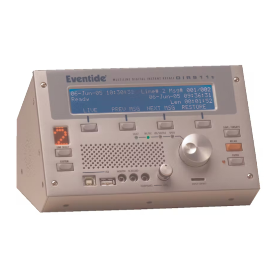
DIR911t
Eventide DIR911t Manuals
Manuals and User Guides for Eventide DIR911t. We have
1
Eventide DIR911t manual available for free PDF download: User Manual
Eventide DIR911t User Manual (97 pages)
Brand:
Eventide
| Category:
Recording Equipment
| Size: 1 MB
Table of Contents
Via the Internet
3
Via Telephone
3
Via Facsimile
3
Via Email
3
Safety Precautions
3
Compliance Information
4
United States FCC Part 68 Telecommunications Statement
4
United States FCC Part 15 Compliance Statement
5
Industry Canada ICES Statement
5
Warranty Information
6
What this Warranty Does and Does Not Cover
6
Who Is Covered under this Warranty
6
When the Warranty Becomes Effective
7
Who Performs the Warranty Work
7
Shipping with the United States or Canada
7
Shipping from Outside the United States or Canada
8
Table of Contents
9
Introduction
19
Front Panel
20
Figure 1: Front Panel Diagram
21
Rear Panel
24
Table 1: Front Panel Legend
24
Figure 2: Rear Panel Diagram
25
Table 2: Rear Panel Legend
28
Installation
29
Unpacking the Unit
29
Installing the Unit
29
Figure 3: Power up Screen
30
Powering down the Unit
31
Figure 4: Boot Screen
31
Figure 5: Main Screen
31
Operation
33
Main Mode
33
Figure 6: Main Screen
33
Table 3: Status Field Descriptions
34
Recall Mode
35
Figure 7: Recall Screen
35
Emailing Messages from Recall Mode
36
System Mode
36
Figure 8: Recall Email Screen
36
Figure 9: System Screen
36
Save to USB Drive
37
Figure 10: Password Screen
37
Figure 11: System Screen
37
Save to USB Drive by Call Number
38
Figure 12: Save Call to USB Drive Screen
38
Figure 13: Save Call to USB Drive by Number Screen
38
Save to USB Drive by Date Range
39
Save to USB Drive by Call Filter
39
Figure 14: Save Call to USB Drive by Date Range Screen
39
Figure 15: Save Call to USB Drive by Call Filter Screen
39
Set Autorestore Time
40
Line Auto Jump Setup
40
High Traffic Mode Setup
40
Figure 16: Autorestore Screen
40
Figure 17: Line Auto Jump Setup Screen
40
Call Filter Use Setup
41
Telephone & AUX Input Gain
41
Figure 18: High Traffic Mode Setup Screen
41
Figure 19: Call Filter Use Setup Screen
41
Automatic Gain Control Setup
42
Monitor and Re-Record Output Level Adjust
42
Figure 20: Telephone and AUX Input Gain Screen
42
Figure 21: AGC Screen
42
Sampling and Compression
43
Figure 22: Monitor and Re-Record Output Level Adjust Screen
43
Figure 23: Telephone Activation Level Screen
43
Recording Priority
44
Figure 24: Recording Priority Screen
44
Table 4: Compression Methods
44
Recording Activation
45
Figure 25: Record Activation Screen
45
Table 5: Line Activation Methods
45
VOX Record Activation Threshold
46
Figure 26: VOX Record Activation Threshold Screen
46
Table 6: Line Activation Methods
46
Set VOX Hold Time
47
Off Hook Activation Level
47
Figure 27: Telephone Activity Hold Time Screen
47
Figure 28: off Hook Activation Level Screen
47
Test External Relay Closure Activation
48
Audible Beep Level
48
Figure 29: Test External Closure Screen
48
Figure 30: Audible Beep Level Screen
48
ALI/ANI Setup
49
Figure 31: ALI/ANI Setup Screen
49
Configure ALI/ANI Serial Ports
50
Centralized Archiving Setup
51
Figure 32: Configure ALI/ANI Serial Ports Screen
51
Figure 33: Centralized Archive Setup Screen
51
Centralized Archive Pointer Setup
52
Centralized Archive Status
52
Figure 34: Centralized Archive Pointer Setup Screen
52
Figure 35: Centralized Archive Status Screen
52
Date/Time Setup
53
Figure 36: Date & Time Setup Screen
53
Ethernet Setup
54
Table 7: Clock Synchronization Methods
54
Email Address Setup
55
Figure 37: Ethernet Setup Screen
55
Figure 38: Email Address Setup Screen
55
Email Server Setup
56
Security Level
56
Figure 39: Email Server Setup Screen
56
Password Setup
57
Figure 40: Security Level Screen
57
Figure 41: Password Setup Screen
57
Add-On License Key
58
Add User
58
Figure 42: Add-On License Key Screen
58
Figure 43: Add User Screen
58
Delete User
59
Configure Line Name
59
Figure 44: Delete User Screen
59
Figure 45: Line Naming Screen
59
Split Mode
60
Import/Export System Configuration
60
Figure 46: Split Mode Screen
60
Figure 47: RAID Import/Export System Configuration Screen
60
Firmware Upgrade
61
Figure 48: Update Screen
61
Raid Status
62
Total Call Count
62
System Halt/Reboot
62
Figure 49: RAID Status Screen
62
Figure 50: Total Call Count Screen
62
System Information Screen
63
System Alerts Screen
63
Figure 51: System Halt/Reboot Screen
63
Figure 52: System Information Screen
63
Figure 53: System Information Screen
64
Call Filter
65
Date and Time Filter
65
Figure 54: Call Filter Setup Screen
65
Incoming Line Filter
66
DTMF Digits Filter
66
Figure 55: Date and Time Filter Screen
66
Figure 56: Incoming Line Filter Screen
66
Caller ID Digits Filter
67
Figure 57: DTMF Digits Filter Screen
67
Figure 58: Caller ID Digits Filter Screen
67
Split Mode
69
Factory Defaults
71
Table 8: Factory Defaults
72
Connector Pinouts
73
Front Panel
73
Figure 59: Front Panel Connector Locations
74
USB a "Host Side" Connector
75
USB B "Peripheral Side" Connector
75
Figure 60: Front Panel USB a Connector Pin Diagram
75
Table 9: Front Panel USB a Connector Pin Description
75
Monitor Output Connector
76
Figure 61: Front Panel USB B Connector Pin Diagram
76
Table 10: Front Panel USB B Connector Pin Description
76
Re-Record Output Connector
77
Figure 62: Front Panel Monitor Connector Pin Diagram
77
Figure 63: Front Panel Re-Record Connector Pin Diagram
77
Table 11: Front Panel Monitor Connector Pin Description
77
Headphone Output Connector
78
Figure 64: Front Panel Headphone Connector Pin Diagram
78
Table 12: Front Panel Re-Record Connector Pin Description
78
Table 13: Front Panel Headphone Connector Pin Description
78
Rear Panel
79
Power Input Connector
81
Figure 65: Rear Panel Connector Locations
81
Figure 66: Rear Panel Connector Locations
81
Figure 67: Rear Panel DC Power Connector Pin Diagram
81
Table 14: Rear Panel DC Power Connector Pin Description
81
Telephone Line Connectors
82
Figure 68: Rear Panel Telephone Line RJ-11 Connector Pin Diagram
82
Table 15: Rear Panel Telephone Line RJ-11 Connector Pin Description
82
Auxiliary Input Connectors
83
ALI Input Connector
83
Figure 69: Rear Panel Auxiliary Input Connector Pin Diagram
83
Table 16: Rear Panel Auxiliary Connector Pin Description
83
ANI Input Connector
84
Figure 70: Rear Panel ALI DB-9 Connector Pin Diagram
84
Table 17: Rear Panel ALI DB-9 Connector Pin Description
84
External Activity Connector
85
Figure 71: Rear Panel ANI DB-9 Connector Pin Diagram
85
Table 18: Rear Panel ANI DB-9 Connector Pin Description
85
Figure 72: Rear Panel External Activity DB-9 Connector Pin Diagram
86
Table 19: Rear Panel External Activity DB-9 Connector Pin Description
86
Time Sync Input / Console Connector
87
Figure 73: Rear Panel Time Sync/Console DB-9 Connector Pin Diagram
87
Table 20: Rear Panel Time Sync/Console DB-9 Connector Pin Description
87
USB a "Host Side" Connectors
88
Ethernet Connector
88
Figure 74: Rear Panel USB a Connector Pin Diagram
88
Table 21: Rear Panel USB a Connector Pin Description
88
Figure 75: Rear Panel Ethernet RJ-45 Connector Pin Diagram
89
Table 22: Rear Panel Ethernet RJ-45 Connector Pin Description
89
Reference Documents
91
Connectors/Connections
91
Protocols
91
Index
93
Advertisement
Advertisement
Related Products
Eventide DIR911
Eventide DSP7000
Eventide 141242
Eventide 1745M
Eventide BD 955
Eventide BD500
Eventide Eclipse
Eventide H8000FW
Eventide H9000
Eventide H9000R
Eventide Categories
Recording Equipment
Music Pedal
Music Equipment
Control Systems
Computer Hardware
More Eventide Manuals
Login
Sign In
OR
Sign in with Facebook
Sign in with Google
Upload manual
Upload from disk
Upload from URL