Sign In
Upload
Download
Table of Contents
Contents
Add to my manuals
Delete from my manuals
Share
URL of this page:
HTML Link:
Bookmark this page
Add
Manual will be automatically added to "My Manuals"
Print this page
×
Bookmark added
×
Added to my manuals
Manuals
Brands
AP Manuals
Controller
CGM
User manual
AP CGM User Manual
Gas controller
Hide thumbs
1
Table Of Contents
2
3
4
5
6
7
8
9
10
11
12
13
14
15
16
17
18
19
20
21
22
23
24
25
26
27
28
29
30
31
page
of
31
Go
/
31
Contents
Table of Contents
Bookmarks
Table of Contents
Table of Contents
Application Intended for Use
Description
Normal Mode
Alarm Mode
Fault Mode
Operating Instruction
Description Keypad User Interface
Setting / Change Parameters or Set Points
Code Levels
Menu Overview
Fault Management
Acknowledge a Fault
Error Memory
System Errors
Status Alarm
Status Relay
Manual Operation of the Relays
Menu Measuring Values
Menu Relay Parameter
Relay Mode
Relay Function Static / Flash
Latching Mode
Horn Function
External Operation of Alarm Relay
Delay Mode of Alarm Relay
Menu MP Parameter
Activate - Deactivate MP
Lock or Unlock MP
Selection Gas Type
Measuring Range Definition
MP Signal Definition
Threshold/ Hysteresis
Delay for Alarm on And/Or off
Control Mode Current or Average Value
MP Fault Assigned to Alarm
4.6.10 Alarm Assigned to Alarm Relay
4.6.11 MP Signal Assigned to Analog Output
Menu Data Logger
Data Logger Switch On/Off
Current Values
CV Log Rate
Alarm Status
Error Status
Menu System Parameter
Service Mode
Software Version
MP Address Mode
Language
Advertisement
Quick Links
Download this manual
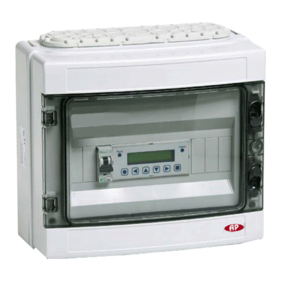
Gas Controller
CGM, CGD,PCR, CG-05
User's Manual
June 2012
AUTOMATIKPRODUKTER
Table of
Contents
Previous
Page
Next
Page
1
2
3
4
5
Advertisement
Table of Contents
Need help?
Do you have a question about the CGM and is the answer not in the manual?
Ask a question
Questions and answers
Related Manuals for AP CGM
Controller AP CGD User Manual
Gas controller (31 pages)
Controller AP TC5-1N5FAB User Manual
Combined ventilation controller (72 pages)
Controller AP Cumberland Feed-Link 2 Installation And Operation Manual
(46 pages)
Controller AP RoboteQ FBL2360A Manual
Advanced features 2 x 60a or 1 x 120a brushless dc motor controller with usb and can (21 pages)
Controller AP TC5-1N4F1A User Manual
Combined ventilation controller (60 pages)
Controller AP TC5-1V6SA User Manual
(55 pages)
Controller AP BM000N Specification & Installation Instructions
(4 pages)
Controller AP UM200 Specification & Installation Instructions
(4 pages)
This manual is also suitable for:
Cgd
Pcr
Cg-05
Table of Contents
Print
Rename the bookmark
Delete bookmark?
Delete from my manuals?
Login
Sign In
OR
Sign in with Facebook
Sign in with Google
Upload manual
Upload from disk
Upload from URL


Need help?
Do you have a question about the CGM and is the answer not in the manual?
Questions and answers