Table of Contents
Advertisement
Quick Links
1
Advanced Features
2 x 60A or 1 x 120A
Brushless DC
Motor Controller
with USB and CAN
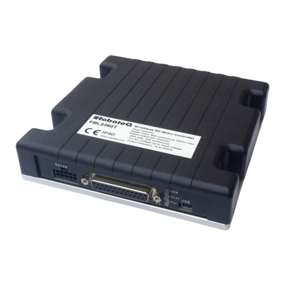
RoboteQ's FBL2360 is a features-packed, high-current, dual
or single channel controller for brushless DC motors. The
controller can operate in one of several modes in order to
sense the rotor position and sequence power on the motor's
3 windings in order to generate smooth continuous rotation.
The controller also uses the Hall sensor and/or Encoder
information to compute speed and measure travelled distance
inside a 32-bit counter. The motors may be operated in open
or closed loop speed mode, position mode or in torque mode.
The FBL2360 features several Analog, Pulse and Digital I/
Os which can be remapped as command or feedback inputs,
limit switches, or many other functions. The FBL2360 accepts
commands received from an RC radio, Analog Joystick,
wireless modem, or microcomputer. For mobile robot
applications, the controller's two motor channels can either be
operated independently or mixed to move and steer a vehicle.
Using CAN bus, up to 127 controllers can be networked at up
to 1Mbit/s on a single twisted pair.
Numerous safety features are incorporated into the controller to
ensure reliable and safe operation. The controller's operation can
be extensively automated and customized using Basic Language
scripts. The controller can be configured, monitored and tuned
in real-time using a RoboteQ's free PC utility. The controller can
also be reprogrammed in the field with the latest features by
downloading new operating software from Roboteq.
Applications
Automatic Guided Vehicles
•
Small Electric Vehicles, Electric Bikes
•
Terrestrial and Underwater Robotic Vehicles
•
Police and Military Robots
•
Hazardous Material Handling Robots
•
Balancing Robots
•
Telepresence Systems
•
Animatronics
•
FBL2360 Brushless DC Motor Controller Datasheet
FBL2360
Key Features
USB, Serial, 0-5V Analog, or Pulse (RC radio) command
•
modes
One RS232 serial port
•
CAN bus interface up to 1Mbit/switch multiple protocol
•
support
RS485
•
Optional Ethernet interface
•
Auto switch between Serial, USB, CAN, Analog, or
•
Pulse based on user-defined priority
Built-in dual 3-phase high-power drivers for two
•
brushless DC motor at up to 60A
Output channels can be paralleled in order to drive a
•
single motor at up to 120A
Multiple Motor Operating mode
•
- Trapezoidal with Hall Sensors
- Sinusoidal with Encoders
- Sinusoidal with Hall Sensors
Support for absolute angle encoders
•
sin/cos analog
•
SSI (A & T version)
•
Resolver (A & T version)
•
Field Oriented Control in Sinusoidal modes
•
Full forward & reverse motor control. Four quadrant
•
operation. Supports regeneration
Operates from a single 10V-60V power source
•
STO - Safe Torque Off support (T-version) - Certification
•
No. M6A 104504 0001 Rev. 00
Design compliant/approval UL 61800-5-1
•
Programmable current limit up to 60A (120Aon single
•
channel version) per motor for protecting controller,
motor, wiring and battery.
Separate connector for Hall Sensors
•
Accurate speed and Odometry measurement using
•
Hall Sensor or Encoder data
FBL2360_1691-21588-0001-D-0720
1
Advertisement
Table of Contents

Related Manuals for AP RoboteQ FBL2360A


Summary of Contents for AP RoboteQ FBL2360A
- Page 1 FBL2360_1691-21588-0001-D-0720 FBL2360 Advanced Features 2 x 60A or 1 x 120A Brushless DC Motor Controller with USB and CAN RoboteQ’s FBL2360 is a features-packed, high-current, dual Key Features or single channel controller for brushless DC motors. The USB, Serial, 0-5V Analog, or Pulse (RC radio) command •...
-
Page 2: Orderable Product References
FBL2360_1691-21588-0001-D-0720 Up to 8 Analog Inputs for use as command and/or feedback Separate Programmable acceleration and deceleration • • for each motor Up to 8 Pulse Length, Duty Cycle or Frequency Inputs • for use as command and/or feedback Ultra-efficient 2.5 mOhm ON resistance MOSFETs •... -
Page 3: Power Wires Identifications And Connection
FBL2360_1691-21588-0001-D-0720 Power Wires Identifications and Connection Important Safety Disclaimer Dangerous uncontrolled motor runaway condition can occur for a number of reasons, including, but not limited to: command or feedback wiring failure, configuration error, faulty firmware, errors in user script or user program, or controller hardware failure. -
Page 4: Important Warning
FBL2360_1691-21588-0001-D-0720 VMot Ground Ground Power Control Controller Power The diagram below shows how to wire the controller and how to turn power On and Off. SW1 Main On/Off Switch 1A PwrCtrl Note 1 Ground Motor1 Backup Battery Diode Resistor Hall >20A 1K, 0.5W Sensors1... -
Page 5: Precautions And Optional Connections
FBL2360_1691-21588-0001-D-0720 Single Channel Wiring Precautions and Optional Connections Note 1: Backup battery to ensure motor operation with weak or discharged batteries, connect a second battery to the Power Control wire/terminal via the SW1 switch. Note 2: Use precharge 1K, 0.5W Resistor to prevent switch arcing. Note 3: Insert a high-current diode to ensure a return path to the battery during regeneration in case the fuse is blown. -
Page 6: Controller Mounting
FBL2360_1691-21588-0001-D-0720 Use of Safety Contactor for Critical Applications An external safety contactor must be used in any application where damage to property or injury to person can occur because of uncontrolled motor operation resulting from failure in the controller’s power output stage. SW1 Main On/Off Switch 1A PwrCtrl... - Page 7 FBL2360_1691-21588-0001-D-0720 Connection to SPI Absolute Encoder TABLE 1. Pin Number Row Ch1 Hall1 C Hall1 B Hall1 A Ground Row Ch2 Hall2 C Hall2 B Hall2 A Ground Hall Sensor vs Motor Output sequencing The controller requires the Hall sensors inside the motor to be 120 degrees apart. The controller’s 3-phase bridge will activate each of the motor winding according to the sequence shown in the figure below.
- Page 8 FBL2360_1691-21588-0001-D-0720 TABLE 2. Pin Number Row 1 Row 2 Clock Data 2 Data 1 Connection to SSI Absolute Encoder In Sinusoidal Mode, the controller can use motors equipped with absolute angle sensors with SSI interface. When enabled, the SSI signals are found on the 10-pin Molex connector that is otherwise used for the Hall Sensors.
- Page 9 FBL2360_1691-21588-0001-D-0720 Commands and I/O Connections Secondary 1 ASIN1 Primary Channel 1 Secondary 2 ACOS1 Secondary 1 ASIN2 Primary Channel 2 Secondary 2 ACOS2 The table below shows the signals assignment on the 25-pin connector. TABLE 5. Signal Pin Number Pin Name Sin1 ASIN1 Cos1...
-
Page 10: Default I/O Configuration
FBL2360_1691-21588-0001-D-0720 TABLE 6. Connector Default Power Dout Pulse Dinput Hall (4) Config 5VOut RS TxD RS232Tx ANA1 DIN1/ Hall1A RCRadio1 (3) STO1 (2) RS RxD RS232Rx ANA2 DIN2/ Hall1B RCRadio2 (3) STO2 (2) ANA3 DIN3 Hall1C AnaCmd1 (1) ANA4/EXC DIN4 Hall2A AnaCmd2 (1) DOUT1... -
Page 11: Usb Communication
FBL2360_1691-21588-0001-D-0720 RS485 Communication how to connect two outputs to motor brake solenoids and another output to an external status LED. You may omit any connection that is not required in your application. The controller automatically arbitrates the command priorities depending on the presence of a valid command signal in the following order: 1-RS232, 2-RC Pulse, 3-None. -
Page 12: Ethernet Communication
FBL2360_1691-21588-0001-D-0720 Ethernet Communication Ethernet communication is currently only available on the E versions of applicable Roboteq product. There is a connection port on the top of the unit for easy and rapid access. While the TCP and Modbus TCP protocols are supported, Serial is the preferred method to access all native commands. - Page 13 FBL2360_1691-21588-0001-D-0720 Safe Torque Off - STO (Certification No. M6A 104504 0001 Rev 00) Measured and Calculated Amps The controller includes Amps sensors in line with the motor terminals. Motor Amps are measured with precision. Battery Amps are estimated mathematically. When motor is rotating, amps are AC. The FBL2360 measures and is rated based on RMS Amps.
- Page 14 FBL2360_1691-21588-0001-D-0720 Important Warning Activating STO does lead to no more torque generation on the motor. The motor will not be actively stopped but run out. In case of a multiple fault in the power stage a rotation might occur. Secure Connection to AMP FASTON™ Tabs Power Motor and Battery connections are made via standard 250mils (6.35mm) AMP FASTON Tabs.
- Page 15 FBL2360_1691-21588-0001-D-0720 Electrical Specifications Power Stage Electrical Specifications (at 25ºC ambient) TABLE 8. Parameter Measure point Model Units Input Voltage Ground to Vmot 0 (1) Volts Input continuous Max Current Power source current Amps Output Voltage Ground to U, V, W wires 0 (1) 60 (2) Volts...
-
Page 16: Command, I/O And Sensor Signals Specifications
FBL2360_1691-21588-0001-D-0720 Command, I/O and Sensor Signals Specifications TABLE 9. Parameter Measure point Units Main 5V Output Voltage Ground to 5V pins on Volts 5V Output Current 5V pins on RJ45 and DSub15 200 (1) Digital Output Voltage Ground to Output pins Volts Output On resistance Output pin to ground... -
Page 17: Thermal Specifications
FBL2360_1691-21588-0001-D-0720 Electrical Specifications Scripting TABLE 11. Parameter Measure Point Units Scripting Flash Memory Internal Bytes Max Basic Language programs Internal 2000 3000 Lines Integer Variables Internal 4096 Words (1) Boolean Variables Internal 8192 Symbols Execution Speed Internal 50 000 100 000 Lines/s Note 1: 32-bit words Thermal Specifications TABLE 12. -
Page 18: Sto Specifications
FBL2360_1691-21588-0001-D-0720 STO Specifications TABLE 13. Parameter Measure Point Units STO Input High Level Ground to STO input pin 30 (1) Volts STO Input Low Level Ground to STO input pin Volts STO Response Time Input to output change msec STO Operating temperature ºC STO Storage temperature ºC... -
Page 19: Revision History
VMOT Ctrl FBL2360_1691-21588-0001-D-0720 Electrical Specifications 5.50" (139.7mm) 0.24" (6.0mm) 1.25" (31.8mm) 3.00" (76.2mm) FIGURE 15. FBL2360 top view and dimensions Revision history Revision Date Additions/Changes Hall Sensors I/O Connector LEDs April 23, 2019 Added T-version with STO support Connector Connector May 21, 2019 STO certification change August 29, 2019... - Page 20 Office Germany: Headquarter Switzerland: Angst+Pfister Sensors and Power Angst+Pfister Sensors and Power AG Deutschland GmbH Edisonstraße 16 Thurgauerstrasse 66 CH-8050 Zurich D-85716 Unterschleißheim Phone +49 89 374 288 87 0 Phone +41 44 877 35 00 sensorsandpower@angst-pfister.com sensorsandpower.de@angst-pfister.com We are here for you. Addresses and Contacts. Sales Germany &...
Need help?
Do you have a question about the RoboteQ FBL2360A and is the answer not in the manual?
Questions and answers