
Related Manuals for AP Cumberland Feed-Link 2


Summary of Contents for AP Cumberland Feed-Link 2
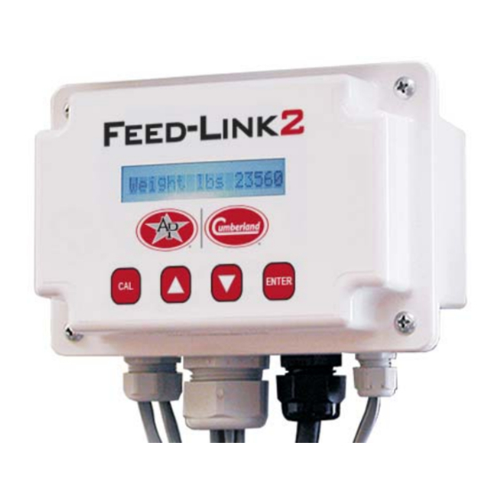
- Page 1 Feed-Link 2 Installation and Operation Manual PNEG-2340 Version: 1.0 Date: 07-22-21 PNEG-2340...
- Page 2 All information, illustrations, photos, and specifications in this manual are based on the latest information available at the time of publication. The right is reserved to make changes at any time without notice. PNEG-2340 Feed-Link 2...
-
Page 3: Table Of Contents
Table of Contents Contents Chapter 1 Getting Started .............................4 Introduction ............................4 Selecting the Load Cell ..........................4 Tools Needed for Installation .........................4 Chapter 2 Safety ..............................5 Safety Guidelines ...........................5 Cautionary Symbol Definitions .......................6 Safety Cautions ............................7 Safety Sign-Off Sheet ..........................9 Chapter 3 Parts Identification ..........................10 Chapter 4 Load Cell Installation .........................13... -
Page 4: Chapter 1 Getting Started
1. Getting Started Introduction READ THIS MANUAL carefully to learn how to properly use and install equipment. Failure to do so could result in personal injury or equipment damage. INSPECT the shipment immediately upon arrival. The customer is responsible for ensuring that all quantities are correct. -
Page 5: Chapter 2 Safety
2. Safety Safety Guidelines Safety guidelines are general-to-specific safety rules that must be followed at all times. This manual is written to help you understand safe operating procedures and problems that can be encountered by the operator and other personnel when using this equipment. Read and save these instructions. As owner or operator, you are responsible for understanding the requirements, hazards, and precautions that exist and to inform others as required. -
Page 6: Cautionary Symbol Definitions
2. Safety Cautionary Symbol Definitions Cautionary symbols appear in this manual and on product decals. The symbols alert the user of potential safety hazards, prohibited activities and mandatory actions. To help you recognize this information, we use the symbols that are defined below. This symbol indicates an imminently hazardous situation DANGER which, if not avoided, will result in serious injury or death. -
Page 7: Safety Cautions
2. Safety Safety Cautions Use Personal Protective Equipment • Use appropriate personal protective equipment: Respiratory Foot Protection Protection Protection Hearing Head Fall Protection Protection Protection Hand Protection • Wear clothing appropriate to the job. • Remove all jewelry. • Tie long hair up and back. ST-0004-1 Follow Safety Instructions •... - Page 8 2. Safety Maintain Equipment and Work Area • Understand service procedures before doing work. Keep area clean and dry. • Never service equipment while it is operating. Keep hands, feet, and clothing away from moving parts. • Keep your equipment in proper working condition. Replace worn or broken parts immediately.
-
Page 9: Safety Sign-Off Sheet
2. Safety Safety Sign-Off Sheet Below is a sign-off sheet that can be used to verify that all personnel have read and understood the safety instructions. This sign-off sheet is provided for your convenience and personal record keeping. Date Employee Name Supervisor Name ST-0007 PNEG-2340 Feed-Link 2... -
Page 10: Chapter 3 Parts Identification
3. Parts Identification Ref # Parts Part # Description INT-4851 Feed-Link 2 Display Unit 24 VDC INT-4853 Feed-Link 2 Display Unit, 110/220V, 50/60 Hz INT-4852 Display Unit Lid Board INT-2100330 Junction Box INT-1100290 Network Master (Includes IYR Service) INT-4850B Display Unit Base Board with Enclosure 24 VDC Display Unit Base Board with Enclosure INT-4814 110/220V, 50/60 Hz... - Page 11 3. Parts Identification Ref # Parts Part # Description Bin Leg Mounting Bracket (for Display Unit and INT-4812 Junction Box) INT-4854 8,000 Lbs. Calibrated Load Cell Assembly INT-4855 12,000 Lbs. Calibrated Load Cell Assembly INT-4825 RF Module INT-4831-100 INT-4831-500 Wire for 24 VDC Power and Communication (Separate Runs for Ea.) 18 Gauge, 2 Cond., Shielded with Drain.
- Page 12 3. Parts Identification Ref # Parts Part # Description INT-4818-25 25' of 10 Wire Cable for Junction Boxes INT-4818-50 50' of 10 Wire Cable for Junction Boxes INT-4818-75 75' of 10 Wire Cable for Junction Boxes INT-4818-100 100' of 10 Wire Cable for Junction Boxes INT-4818 1000' of 10 Wire Cable for Junction Boxes Low Voltage (24 VDC) Transformer...
-
Page 13: Chapter 4 Load Cell Installation
4. Load Cell Installation Removing Anchor Nuts 1. Use a 3/4" wrench or crescent to remove the nut and washer from the anchor bolt on the bin leg. (See Figure 4A.) 2. Remove the side bolts using 9/16" wrench and impact wrench or ratchet. -
Page 14: Raising The Bin
4. Load Cell Installation Raising the Bin 1. Place 4 x 4 spanner board under bin hopper braces. (See Figure 4D.) 2. Center lift jack under 4 x 4 spanner brace. (See Figure 4D.) 3. Lift bin with jack about 4". This should lift two (2) bin legs. -
Page 15: Installing The Load Cell Base
4. Load Cell Installation Installing the Load Cell Base 1. Shortening the anchor bolt may be required. It can protrude no more than 1-1/4" above the foundation. (See Figure 4F.) NOTE: You may find it easier to put the nut on the bolt and cut the bolt flush with the nut. -
Page 16: Install Load Cell And Attach To The Bin Leg
4. Load Cell Installation Install Load Cell and Attach to the Bin Leg 1. Place the load cell into the load cell base, lining up the holes. Line up the holes in the side of the load cell with the holes in the side of the load cell base. -
Page 17: Running Load Cell Cables
4. Load Cell Installation Running Load Cell Cables 1. Label both ends of the load cell cable with the load cell number. Numbers will range from 1 through 8. Labeling the load cell cables will identify what terminals to use when connection wires to display unit in installing the stand alone display units on Page... -
Page 18: Chapter 5 Installing The Stand Alone Display Units
5. Installing the Stand Alone Display Units Mounting Display and Junction Boxes The display can be mounted either directly onto the bin leg or remotely, up to 1000' away, such as inside a nearby building. When mounted remotely, a junction box must be used to extend the load cell wires from the bin to the display unit. -
Page 19: Installing The Stand Alone Bin Mounted Display Units
5. Installing the Stand Alone Display Units Always make sure all power is disconnected and locked out while display unit cover is OFF. Installing the Stand Alone Bin Mounted Display Units 1. Connect the load cell wires as below. a. Slide all the load cell cables through the grommet cap. - Page 20 5. Installing the Stand Alone Display Units Installing the Stand Alone Bin Mounted Display Units (Continued) Figure 5F Display and Load Cell Wiring Diagram PNEG-2340 Feed-Link 2...
- Page 21 5. Installing the Stand Alone Display Units Installing the Stand Alone Bin Mounted Display Units (Continued) 2. Connect the power wires. a. Each display unit requires 24 VDC power. Refer to wiring diagram, see Figure b. Run two (2) conductor, 18 AWG cable with ground from 24 VDC transformer to display unit as shown in the wiring diagram Figure c.
-
Page 22: Chapter 6 Remote Mounted Display Units With Junction Box
6. Remote Mounted Display Units with Junction Box Connecting the Load Cells to the Junction Box Always make sure all power is disconnected and locked out while any electrical work is being performed. NOTE: If display units are mounted inside, then you will need a junction box. -
Page 23: Connecting The Ten (10) Conductor Cable To The Display Unit
6. Remote Mounted Display Units with Junction Box Connecting the Ten (10) Conductor Cable to the Display Unit The maximum distance, the display unit can be mounted away from the junction box is 1000'. Insert the ten (10) conductor cable through the large single-hole grommet in the bottom center of the display unit. The ten (10) conductor cable connects to the top eight (8) terminal connector at the top center of the display unit and the two (2) terminal connector labeled “12 VDC Out”... -
Page 24: Chapter 7 Networking
7. Networking Explanation of Daisy Chain Network A daisy chain network consists of a group of display units connected together in series by RS485 cables. A Network Master can be connected at any point in the daisy chain, such as in illustrations 4 in Figure 7C on Page 25 or the example daisy chains such as in illustrations... -
Page 25: Optional Networking Layouts
7. Networking Optional Networking Layouts Layout with display units mounted inside building with Network Master located within the daisy chain. Maximum display units per Network Master is 50. Network cable not to exceed 4000' in total length. Load cell wires (can be up to 8 load cells) Maximum length from display units... -
Page 26: Network Wiring Of Display Unit
7. Networking Network Wiring of Display Unit Always make sure all power is disconnected and locked out while any electrical work is being performed. NOTE: Maximum of 50 display units per Network Master. Maximum network wire length is equal to 4000'. Wire Specs: Use INT-4831-100, INT-4831-500 or INT-4831-1000 (18 gauge, 2 conductor, shielded, with a drain wire). -
Page 27: Network Master Wiring
7. Networking Network Master Wiring The Network Master is a hardware device used to Network Master Technical Specifications: connect all display units at a location over a RS485 Supply: 24 VDC, 50/60 Hz, overload and over network, so feed inventory and water consumption voltage protection fuses F1, F2-1/4A slow blow. -
Page 28: Connecting The Rs485 Network Cables To The Network Master
7. Networking Connecting the RS485 Network Cables to the Network Master Use 18 AWG shielded, two conductor RS485 cable from RS485 out cable on the display unit, connect white wire to terminal marked “A” on back of the Network Master. Connect the black wire to the terminal marked “B”... -
Page 29: Chapter 8 Water Meter Option
8. Water Meter Option Optional Water Meter (One gallon per pulse) 1. Hook water meter wires to the display unit. a. Run the water meter cable through the bottom left water tight nut. b. Remove the terminal strip. (See Figure 8A.) c. - Page 30 8. Water Meter Option Optional Water Meter (Continued) Figure 8B Display and Load Cell Wiring Diagram PNEG-2340 Feed-Link 2...
-
Page 31: Chapter 9 Rf Module Option
9. RF Module Option The RF module allows wireless communication between the display units and the Network Master without having to run wires. Things to consider before installation: • Never route any communication wires parallel to a high voltage power line. Power lines will create noise and cause interference with the signal. -
Page 32: Mount Rf Module To The Outside Of The Building
9. RF Module Option Mount RF Module to the Outside of the Building 1. Fasten RF module to structure using 2 x 6 treated lumber. Mount RF module high enough for a clear line of sight to all other RF modules. -
Page 33: Connecting Wires To The Rf Module
9. RF Module Option Connecting Wires to the RF Module Connect Wires to the Display Unit Connect the power cable to “24 VDC” terminal strip on the right hand side of the display unit. Connect the white wire from the power cable to the terminal marked “+”. Connect the black wire to the terminal marked “-”. - Page 34 9. RF Module Option Connect Wires to a Network Master Connect the power cable to “24 VDC” terminal strip on the back right hand side of the Network Master. Connect the white wire from the power cable to the terminal marked “24 VDC +”. Connect the black wire to the terminal marked “24 VDC -”.
-
Page 35: Possible Rf Module Layouts
9. RF Module Option Possible RF Module Layouts This example shows the bins of each This example shows all the bins networked building networked together as a group and together as a group and then wired to one then wired to a RF module. These RF RF module. -
Page 36: Chapter 10 Display Unit Calibration And Setup
10. Display Unit Calibration and Setup Figure 10A Display Unit Calibration and Setup Features FOR CUSTOMER USE Enter the serial number located on the side of the The INT-4851 and INT-4853 is a display unit used display unit below for future use. to display the weight of feed in a bin. -
Page 37: Display Unit Setup
10. Display Unit Calibration and Setup Display Unit Setup NOTE: After installation an EMPTY BIN calibration must be performed. After a known amount of feed is added, a FULL BIN calibration can be performed, but it is not necessary, as the load cells are pre-calibrated. - Page 38 10. Display Unit Calibration and Setup Configuration Menus 1. Initial Configuration parameters - Upon first power-up, the display will automatically be in the Configuration Menus. It will show “Load Cells: 8K”, which is the Load Cell Type menu, and is the first menu in a sequence of required configuration parameters.
- Page 39 Use this menu only when the weight of the empty tank needs to be adjusted while it is not empty*. If you do not know the actual weight of the empty bin, contact your AP/Cumberland dealer or Sales EmtyBin lb: 03500 Representative. The default value (first power up after installation) is 0.
- Page 40 10. Display Unit Calibration and Setup Explanation of Configuration Menus (Continued) Load Cells: 8K There are two Load Cell types; 8,000 lbs. per leg (8K) and 12,000 lbs. per leg (12K). The 8K is the default setting. If the bin has 12K load cells, press Load Cells: the up or down arrow button to adjust your selection.
-
Page 41: Troubleshooting Display Unit
10. Display Unit Calibration and Setup Troubleshooting Display Unit General LC Error n The display unit will evaluate the signals from each load cell, for each load cell the user has enabled via the Configuration Menus. If a bad load cell is detected, the normal display will flash the weight calculated using the good load cells and display an error message indicating the bad load cells. - Page 42 10. Display Unit Calibration and Setup Testing Feed-Link Load Cells with a Volt/Ohm Meter (Continued) With the Meter on Ohms and dial on 20K setting With the black meter probe on red load cell wire and the red meter probe on the white load cell wire the meter should have no reading = GOOD CELL.
-
Page 43: Chapter 11 Feed-Link Network Master
11. Feed-Link Network Master For information on installation, set-up and operation of Network Master, refer to Network Master operation manual PNEG-1855. PNEG-2340 Feed-Link 2... - Page 44 NOTES PNEG-2340 Feed-Link 2...
-
Page 45: Chapter 12 Warranty
12. Warranty Limited Warranty - Protein Products The GSI Group, LLC. (“GSI”) warrants products which it manufactures, to be free of defects in materials and workmanship under normal usage and conditions for a period of 12 months from the date of purchase (or, if shipped by vessel, 14 months from the date of arrival at the port of discharge). - Page 46 This equipment shall be installed in accordance with the current installation codes and applicable regulations, which should be carefully followed in all cases. Authorities having jurisdiction should be consulted before installations are made. 1004 E. Illinois St. Assumption, IL 62510-0020 Phone: 1-217-226-4421 Fax: 1-217-226-4420 www.automatedproduction.com / www.cumberlandpoultry.com...
Need help?
Do you have a question about the Cumberland Feed-Link 2 and is the answer not in the manual?
Questions and answers