Table of Contents
Advertisement
Quick Links
1.
SILENCE
2.
RESET
3.
ISOLATE
4.
SELECT
ISOLATE
SELECT
ISOLATE
FIRE FIGHTER'S GUIDE
SILENCING BELLS
Press "SILENCE" key once.
-
ALL flashing red "ALM" LEDs will go steady
-
Local Bells will be silenced
-
The internal sounder will be silenced if no fault
condition exists.
-
Any new alarm will cause the bells to ring again
and the appropriate zone alarm LED to flash.
RESETTING ALL ZONES IN ALARM
Press "SELECT" key, if required, until all green "SEL" LEDs are
OFF, then press "RESET" key once.
-
ALL flashing or steady red "ALM" LEDs turn OFF.
-
Zone(s) still in alarm will be indicated again.
ISOLATING ALL ZONES IN ALARM
Press "SELECT" key, if required, until all green "SEL" LEDs are
OFF, then press "ISOLATE" key once.
-
ALL flashing red "ALM" LED indicators will go steady
and amber "ISO" LEDs will turn ON.
-
DE-ISOLATING ZONE WILL RE-ACTIVATE BELLS
ISOLATING SELECTED ALARM ZONE
Press "SELECT" key until the required zone's green "SEL" LED
is ON, then press "ISOLATE" key once.
-
Amber "ISO" LED will turn ON.
-
IF A FALSE ALARM, CALL THE MAINTENANCE
COMPANY RESPONSIBLE FOR THE FIRE ALARM
SYSTEM.
3.
RING SILENCED BELLS
Press "SELECT" key until a ZONE IN ALARM is SELECTED.
(Green "SEL" LED is ON)
If amber "ISO" LED is ON, press "ISOLATE" key ONCE.
If amber "ISO" LED is OFF, press "ISOLATE" key TWICE.
-
Amber "ISO" LED indicator will be OFF.
-
Bells are operated.
Advertisement
Table of Contents

Related Manuals for Tyco F08 FIP


Summary of Contents for Tyco F08 FIP
- Page 1 FIRE FIGHTER’S GUIDE SILENCING BELLS Press “SILENCE” key once. ALL flashing red “ALM” LEDs will go steady SILENCE Local Bells will be silenced The internal sounder will be silenced if no fault condition exists. Any new alarm will cause the bells to ring again and the appropriate zone alarm LED to flash.
- Page 2 THIS PAGE INTENTIONALLY LEFT BLANK...
- Page 3 Information contained in this document is copyright, and shall not be reproduced in any form whatsoever, or its contents disclosed to any third party, without the written consent of Tyco Services Fire & Safety (The Company). Information contained in this document is believed to be accurate and reliable, however the...
-
Page 4: Installation Details
F08 Operator's Manual Document No: LT0054 INSTALLATION DETAILS 3. W A R N I N G – The F08 is approved to AS/NZS 3548 Class A. In a domestic environment it may cause radio interference in which case the user may be required to take adequate measures. For your reference please complete the following information on the F08 Fire Indicator Panel supplied. -
Page 5: Table Of Contents
Document No: LT0054 F08 Operator's Manual TABLE OF CONTENTS INSTALLATION DETAILS ....................ii AMENDMENT LOG ......................vi 1 SYSTEM DESCRIPTION....................1-1 1.1 OVERVIEW........................1-2 1.2 DISPLAY PANEL ......................1-4 1.3 COMMAND KEYS ......................1-7 2 SPECIFICATIONS......................2-1 2.1 SYSTEM ........................2-2 2.2 PHYSICAL........................2-3 2.3 ELECTRICAL ........................ - Page 6 F08 Operator's Manual Document No: LT0054 5.4 ANCILLARY RELAY FAULT RESET ................5-5 5.5 OUTPUT TEST & MAPPING DISPLAY ................ 5-6 6 ZONE OPERATING FUNCTIONS..................6-1 6.1 ZONE TEST........................6-2 6.2 ZONE ISOLATE/DE-ISOLATE..................6-4 6.3 AUTO-RESET MODE (One Person Detector-in-Situ Test) ........6-5 7 PLACING INTO OPERATION..................
-
Page 7: Amendment Log
Document No: LT0054 F08 Operator's Manual AMENDMENT LOG ISSUE DATE AMENDMENT 04/05/92 Revised and upgraded from Document 696-002 (Issue 1 Amdt 1) to VIGILANT Document LT0054. 27/05/98 Converted to WORD format. 27/10/98 Modified for V3.00 software, 15V MCP and M614 2769 detectors. - Page 8 F08 Operator's Manual Document No: LT0054 THIS PAGE LEFT INTENTIONALLY BLANK Page vi 24 March 2006 Issue 3.05...
-
Page 9: System Description
Document No: LT0054 F08 Operator's Manual System Description SYSTEM DESCRIPTION Issue 3.05 24 March 2006 Page 1-1... -
Page 10: Overview
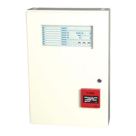
F08 Fire Indicator Panel, according to Australian Standards AS1603 Part 4. This manual is provided as standard with the F08 FIP. Part Numbers are LT0080 in A4 size, or LT0054 in A5, that will fit inside the F08 FIP. - Page 11 Document No: LT0054 F08 Operator's Manual System Description LEGEND Zone Display Output Display Battery/Charger ) VIEWED THROUGH CABINET WINDOW and Mains Status Display Command Keypad Cabinet Key Lock Manual Call Point Figure 1.1 F08 Fire Indicator Panel Issue 3.05 24 March 2006 Page 1-3...
-
Page 12: Display Panel
System Description DISPLAY PANEL 1.2.1 GENERAL The F08 FIP display panel and keypad is shown in Figure 1.2. The LEDs on the display show the status of each alarm zone circuit (AZC), the power supply and the outputs. An internal sounder (buzzer) is used to alert the operator of certain conditions. By pressing the control keypad the operator can perform such functions as: silence the bells;... - Page 13 Document No: LT0054 F08 Operator's Manual System Description 1.2.2 ALARM ZONE INDICATORS The 8 zone LED indicators are at the left-hand side of the display. Each zone has four indicators and space for an installation dependent identification text. Figure 1.3 shows the eight zone block.
- Page 14 Figure 1.4 F08 FIP Status & Common Output LED Indicators The LED indicators may be unlit, flashing, or lit steadily. In normal operation all LEDs are unlit, with the exception of the green "MAINS ON" LED indicator which is steadily lit. The meaning of the indications are: Green "SEL"...
-
Page 15: Command Keys
When battery/charger is selected; a battery test may be performed. The F08 FIP will automatically TIME-OUT to GLOBAL mode if no key is pressed for four (4) minutes and there are no alarms or faults on non-isolated zones. - Page 16 F08 Operator's Manual Document No: LT0054 System Description COMMAND KEYS (CONTINUED) This key is for FIRE FIGHTER'S use. In an ALARM condition pressing this key will acknowledge all zones in SILENCE alarm. It will also de-activate the "ALARM BELLS" output and silence the pulsing-tone alarm sounder.
-
Page 17: Specifications
Document No: LT0054 F08 Operator's Manual Specifications SPECIFICATIONS Issue 3.05 24 March 2006 Page 2-1... -
Page 18: System
F08 Operator's Manual Document No: LT0054 Specifications SYSTEM 2.1.1 CAPACITY Maximum Input Circuits 2.1.2 OPERATING CONDITIONS Ambient temperature Range -5°C - 45°C Maximum Relative Humidity 95% at 40°C Non-Condensing 2.1.3 DETECTOR CIRCUITS Cable Termination Size 0.75 to 2.5 Square Millimetres Voltage with EOL 22.5 to 22.80Vdc (22.7Vdc nom) Loop Resistance... -
Page 19: Physical
Document No: LT0054 F08 Operator's Manual Specifications OUTPUT (CONTINUED) Supervised Output The Ancillary Output "ANCIL" can be wired for supervision of the load and the wiring to it. Output Supplies 0 VDC - Battery Backed +VNB - Non Battery Backed Bells Output 1 switched VB "BELLS"... -
Page 20: Electrical
F08 Operator's Manual Document No: LT0054 Specifications ELECTRICAL Mains Supply 240 VAC, +6% -10%, 50Hz, 100 VA (0.4A) MAX VB & Charger Voltage 27.3* VDC nominal at 20°C Battery-Backed Output VNB Output 27.9* VDC nominal at 20°C Non Battery-Backed * Temperature Compensation -36 mV per °C Current Limit 2.5 Amp to 3 Amp (DC) -
Page 21: Interpreting The Displays
Document: LT0054 F08 Operator's Manual Interpreting The Displays INTERPRETING THE DISPLAYS Issue 3.05 24 March 2006 Page 3-1... -
Page 22: System Normal
F08 Operator's Manual Document: LT0054 Interpreting The Displays SYSTEM NORMAL The Fire Indicator panel is normal when it is not sensing any alarms or faults in the system wiring, the mains power supply is operating normally and the battery is at normal charge voltage. -
Page 23: Dealing With Faults
Document: LT0054 F08 Operator's Manual Interpreting The Displays DEALING WITH FAULTS 3.3.1 WHAT IS A FAULT? A fault is anything which prevents the panel from correctly performing its functions. Possible faults include defects in external wiring or power feed to the detectors and outputs, faulty detectors, component failures, faulty charger and low battery voltage. -
Page 24: Zone Indications
F08 Operator's Manual Document: LT0054 Interpreting The Displays ZONE INDICATIONS 3.4.1 ZONE “SEL” LED INDICATOR The green "SEL" indicator for each zone is interpreted as: Normal, zone not selected. FLASHING Indicates zone has been selected for AUTO-RESET test mode ("ISO" LED also flashing) or Zone test has been activated. Indicates that the zone has been selected for Zone Test, Reset, or Isolate functions. -
Page 25: System Status Indicators
Document: LT0054 F08 Operator's Manual Interpreting The Displays SYSTEM STATUS INDICATORS 3.5.1 “MAINS ON” LED INDICATOR The green "MAINS ON" indicator is interpreted as: Normal condition indicating mains power is present. Indicates that the mains supply to the FIP has been interrupted. Possible reasons are: The council mains supply is out. -
Page 26: Output Indicators
F08 Operator's Manual Document: LT0054 Interpreting The Displays OUTPUT INDICATORS 3.6.1 OUTPUT“SEL” LED INDICATOR The three green "SEL" indicators for ANCIL RELAY, MASTER ALARM and ALARM BELLS can be interpreted as: Normal, output not selected. Indicates that the output has been selected and that Test, Reset or Isolate functions may be carried out. -
Page 27: Brigade Operating Functions
Document: LT0054 F08 Operator's Manual Brigade Operating Functions BRIGADE OPERATING FUNCTIONS Issue 3.05 24 March 2006 Page 4-1... -
Page 28: Resetting Zone(S) In Alarm Or Fault
F08 Operator's Manual Document: LT0054 Brigade Operating Functions RESETTING ZONE(S) IN ALARM OR FAULT 4.1.1 FUNCTION Pressing the "RESET" key performs the following functions: In GLOBAL mode it will: RESET ALL ZONES IN ALARM Silence the alarm sounder Exit from System Test Return all Auto-Reset zones to normal. -
Page 29: Silencing Zone(S) In Alarm Or Fault
Document: LT0054 F08 Operator's Manual Brigade Operating Functions SILENCING ZONE(S) IN ALARM OR FAULT 4.2.1 FUNCTION Pressing the "SILENCE" key performs the following functions: IN ALARM CONDITION: Acknowledges all ALARMS shown on the panel; Silences the pulsing-tone alarm sounder iii. Turns off the ALARM BELLS output. -
Page 30: Isolating Zone(S) In Alarm
F08 Operator's Manual Document: LT0054 Brigade Operating Functions ISOLATING ZONE(S) IN ALARM 4.3.1 FUNCTION Pressing the "ISOLATE" key performs the following functions: In GLOBAL mode it will ISOLATE ANY ZONE(S) IN ALARM. With a Zone, Ancillary Relay or Alarm Bells selected it will toggle the zone or output between isolated and non-isolated states. -
Page 31: System Operating Functions
Document No: LT0054 F08 Operator's Manual System Operating Functions SYSTEM OPERATING FUNCTIONS Issue 3.05 24 March 2006 Page 5-1... -
Page 32: System Test
System Operating Functions SYSTEM TEST 5.1.1 FUNCTION With the F08 FIP in GLOBAL mode (ie. all "SEL" LED indicators OFF), pressing the "TEST" key will perform the following functions as part of the System Test. All outputs are isolated; The system memory is tested;... -
Page 33: Battery Test
Document No: LT0054 F08 Operator's Manual System Operating Functions BATTERY TEST 5.2.1 FUNCTION When Battery/Charger is selected pressing the "TEST" key performs a 1 minute test of the battery. 5.2.2 OPERATING SEQUENCE Press the "SELECT" key until the green "SEL" LED indicator of "BATT/CHGR"... -
Page 34: Output Isolate/De-Isolate
F08 Operator's Manual Document No: LT0054 System Operating Functions OUTPUT ISOLATE/DE-ISOLATE 5.3.1 FUNCTION When Ancillary Relay, or Alarm Bells is selected, pressing the "ISOLATE" key will toggle the selected output between the isolated or non-isolated states. 5.3.2 OPERATING SEQUENCE Press the "SELECT" key until the green "SEL" LED indicator of the ANCIL RELAY or ALARM BELLS output is illuminated (as required). -
Page 35: Ancillary Relay Fault Reset
Document No: LT0054 F08 Operator's Manual System Operating Functions ANCILLARY RELAY FAULT RESET 5.4.1 FUNCTION When Ancillary Relay is selected pressing the "RESET" key will reset the fault indication on the Ancillary Relay Output if it was illuminated. 5.4.2 OPERATING SEQUENCE Press the "SELECT"... -
Page 36: Output Test & Mapping Display
F08 Operator's Manual Document No: LT0054 System Operating Functions OUTPUT TEST & MAPPING DISPLAY 5.5.1 FUNCTION When the Ancillary Relay, Master Alarm or Alarm Bells is selected pressing the "TEST" key performs the following functions: Displays the zones programmed (mapped) to activate the selected output. Activates the selected output, with the exception of Master Alarm Brigade Relay. -
Page 37: Zone Operating Functions
Document No: LT0054 F08 Operator's Manual Zone Operating Functions ZONE OPERATING FUNCTIONS Issue 3.05 24 March 2006 Page 6-1... -
Page 38: Zone Test
F08 Operator's Manual Document No: LT0054 Zone Operating Functions ZONE TEST 6.1.1 FUNCTION When a zone is selected, indicated by the zone’s green "SEL" LED being illuminated, pressing the "TEST" key will perform a fault and then an alarm test on the zone input. WARNING: This test performs a true zone test, time delays operate (including AVF &... - Page 39 Document No: LT0054 F08 Operator's Manual Zone Operating Functions 6.1.4 EXIT TEST - LEAVE IN FAULT When the zone is in FAULT TEST, double press the "SILENCE" key. The amber "FLT" LED indicator will remain illuminated SILENCE (FOR LATCHING ZONES ONLY). "SELECT"...
-
Page 40: Zone Isolate/De-Isolate
F08 Operator's Manual Document No: LT0054 Zone Operating Functions ZONE ISOLATE/DE-ISOLATE 6.2.1 FUNCTION When a zone is selected pressing the "ISOLATE" key will toggle the zone between isolated or non-isolated states or vice versa. 6.2.2 OPERATING SEQUENCE Press the "SELECT" key until the green "SEL" LED indicator of the required zone is illuminated. -
Page 41: Auto-Reset Mode (One Person Detector-In-Situ Test)
Document No: LT0054 F08 Operator's Manual Zone Operating Functions AUTO-RESET MODE (One Person Detector-in-Situ Test) 6.3.1 FUNCTION The Auto-Reset Test allows testing of all detectors on a zone without the need for a second person resetting the alarms at the FIP. One or more zones can be set to AUTO-RESET mode at the same time. - Page 42 F08 Operator's Manual Document No: LT0054 Zone Operating Functions 6.3.3 OPERATION On alarm operation of a detector and after the 2 second transient suppression delay the zone will go into the alarm condition and stay in that condition for 8 seconds to allow the detector LED to be checked.
-
Page 43: Placing Into Operation
Document No: LT0054 F08 Operator's Manual Placing into Operation PLACING INTO OPERATION Issue 3.05 24 March 2006 Page 7-1... -
Page 44: General
(see Figure 7.1). MAINS ISOLATE SWITCH To switch the F08 FIP ON or OFF open the front protective door. The "MAINS ISOLATE SWITCH" is located below the main board, to the right of the mains transformer. This switch controls the mains power supply to the panel, including the battery charger. -
Page 45: Power Up
Document No: LT0054 F08 Operator's Manual Placing into Operation POWER UP To place a correctly installed F08 FIP into operation perform the following steps: STEP 1: Ensure that the Mains Isolate Switch is OFF. STEP 2: Ensure that 240 VAC is available to the panel from the mains distribution switchboard. - Page 46 F08 Operator's Manual Document No: LT0054 Placing into Operation 7.4.2 ELECTRICAL Transformer fitted and outputs wired correctly Mains Switch fitted & wired correctly, Cover secured All cabinet earths wired correctly and securely fitted "Mains Isolate Switch" and "Mains Earth" labels fitted Mains Earth wired correctly and securely fitted Display FRC cable neat and plugged firmly into main board Bells fuse - F1: Fitted &...
- Page 47 Document No: LT0054 F08 Operator's Manual Placing into Operation 7.4.3 OPERATION NORMAL OPERATION - Green "MAINS ON" LED only ON System Test OK Battery Test OK MCP wired to Zone 1; Other: Operation OK "ALM" LED on MCP Zone flashes & pulsing tone sounder Pressing "RESET"...
- Page 48 F08 Operator's Manual Document No: LT0054 Placing into Operation 7.4.4 FINAL CHECK As Installed Information Drawings Provided As Installed Device Connection List Provided Installation Information completed on page ii of Operator's Manual Presentation (Interior neat, clean) Rating Label completed System Configuration Chart (Appendix D) Completed Operator's Manual Provided (STANDARD) Technical Manual Provided (OPTIONAL) Log Book Provided (Commissioning Details Entered)
-
Page 49: System Maintenance & Trouble-Shooting
Document No: LT0054 F08 Operator's Manual System Maintenance & Trouble-shooting SYSTEM MAINTENANCE & TROUBLE-SHOOTING Issue 3.05 24 March 2006 Page 8-1... -
Page 50: System Maintenance
System Maintenance & Trouble-Shooting SYSTEM MAINTENANCE The F08 FIP is designed for high reliability and minimum maintenance. However, in order to comply with the requirements of AS1851.8, the owner/occupier (or a nominated representative) must carry out system tests on a regular basis. -
Page 51: Trouble-Shooting
Document No: LT0054 F08 Operator's Manual System Maintenance & Trouble-shooting TROUBLE-SHOOTING 8.2.1 PRELIMINARY INVESTIGATIONS These preliminary investigations are to prevent unnecessary service calls, or in the event of a genuine call, to save time and provide the service company with accurate data. It is desirable that the owner/occupier carry out the following checks before requesting service: UNWANTED ALARMS:... - Page 52 F08 Operator's Manual Document No: LT0054 System Maintenance & Trouble-Shooting CONDITION REASON ACTION MAINS SWITCH OFF Turn Mains Switch ON REPORTED POWER Check that LED turns ON when “MAINS ON” BLACKOUT power is restored LED OFF ACCIDENTAL TRIPPED Reset Circuit Breaker & check CIRCUIT BREAKER “MAINS ON”...
-
Page 53: Appendix Acompatible Actuating Devices
Document No: LT0054 F08 Operator's Manual Appendicies APPENDIX A COMPATIBLE ACTUATING DEVICES OLSEN RANGE MAX NO. OF DETECTORS TYPE DESCRIPTION PER ZONE C23BEx * Ionisation Smoke Detector (IS Version) C24B Ionisation Smoke Detector C29B Ionisation Smoke Detector C29BEx Ionisation Smoke Detector (IS Version) P24B Photoelectric Smoke Detector P29B... - Page 54 F08 Operator's Manual Document No: LT0054 Appendicies DETECTORS CERTIFIED WITH THE F08 FOR MAX NO. OF HAZARDOUS AREA APPLICATIONS DETECTORS TYPE DESCRIPTION Iq uA PER ZONE C29BEx # Ionisation Smoke Detector Z94C Base R24BEx # Dual Spectrum InfraRed Flame Detector T54B Probe Type E Heat Detector T56B...
- Page 55 Detectors indicated by a “^” have not been SSL/CSIRO accessed for compatibility. Detectors indicated by a “@” cannot have their remote indicator outputs wired in common with Tyco 614 series or the Minerva M614 series (and most other Tyco/ Olsen detectors).
- Page 56 F08 Operator's Manual Document No: LT0054 Appendicies THIS PAGE LEFT INTENTIONALLY BLANK 24 March 2006 Issue 3.05...
-
Page 57: Appendix Bcompatible Batteries
Document No: LT0054 F08 Operator's Manual Appendicies APPENDIX B COMPATIBLE BATTERIES The following series of batteries are compatible with the F08 FIP: Sonnenschien A200 series Sonnenschien A300 series Power-Sonic PS12 series Yuasa NP Series Note: For large size batteries a battery box may be required. -
Page 58: Appendix Csystem Configuration
F08 Operator's Manual Document No: LT0054 Appendicies APPENDIX C SYSTEM CONFIGURATION System Name: ____________________________________ Battery Type: ____________________________________ Battery Rating: 2 x 12 Volt ______ AH Complete Table C.1 NOTES: Each zone enabled is indicated by a "X". Zone is either non-latching or latching, indicated by a "X". Zone Delay is indicated by an "X". - Page 59 Document No: LT0054 F08 Operator's Manual Appendicies PROGRAMMING ZONE NUMBER ZONE INPUT ENABLED: ZONE INPUTS: Latching Non-Latching (Tracking) INPUT TIME DELAY TYPE: Standard, delay into alarm 2 seconds. 15V MCPs allowed on circuit. AVF/RAD (Return Air Detector). Delay 16 seconds into Alarm, MCP 2 seconds.
- Page 60 F08 Operator's Manual Document No: LT0054 Appendicies THIS PAGE LEFT INTENTIONALLY BLANK 24 March 2006 Issue 3.05...
Need help?
Do you have a question about the F08 FIP and is the answer not in the manual?
Questions and answers