
Related Manuals for Colasit CMVpro 125-400 ATEX


Summary of Contents for Colasit CMVpro 125-400 ATEX
- Page 1 Operating instructions CMVpro 125-400 ATEX Centrifugal fan Your point of contact: Colasit Representative Street Location Version 1-en | 11/2021...
- Page 2 Date Name 1-en EU/ATEX First version published. 11/30/2021 A. Roth Document identification Translation of the original German operating instructions. Colasit TD-000828 Contact information Manufacturer COLASIT AG Faulenbachweg 63 CH-3700 Spiez E-mail: info@colasit.ch Phone: +41 (0)33 655 61 61 Importer Name...
-
Page 3: Table Of Contents
Explosion protection.................... Explosion protection measures ................Explosion protection marking ................. Structure and function ..................Overview......................... Signs and warning symbols on the fan..............Options and accessories ..................5.3.1 Vibration absorbers..................Operating instructions CMVpro 125-400 ATEX | Version 1-en 3 / 88... - Page 4 Motor protection switch installation ............8.2.3 PTC thermistor tripping device installation..........8.2.4 Starting current limiter................Instructions for frequency converter (FC) use ............8.3.1 Frequency converter (FC) installation options ........... 4 / 88 Operating instructions CMVpro 125-400 ATEX | Version 1-en...
- Page 5 12.7 Electric motor exchange ..................12.8 Check impeller......................12.9 Hub seal (option) replacement ................Removal from service, disposal, and recycling ..........13.1 Safety instructions ....................13.2 Environmental protection..................13.3 Removal from service..................... Operating instructions CMVpro 125-400 ATEX | Version 1-en 5 / 88...
- Page 6 Table of contents 13.4 Disposal instructions....................EU - Declaration of conformity................ATEX - Declaration of Conformity............... 15.1 ATEX test report ..................... Index ........................6 / 88 Operating instructions CMVpro 125-400 ATEX | Version 1-en...
-
Page 7: Operating Instruction Information
For the sake of simplification, in these operating instructions, • the company Colasit AG is referred to as the “manufacturer,” • the CMVpro 125-400 ATEX centrifugal fan is referred to as the “fan,” • “frequency converter” is abbreviated as “FC,”... -
Page 8: Copyright
The use and distribution of the operating instructions is permitted in the context of using the fan. Any other use is only permitted with the written consent of the manufacturer. 8 / 88 Operating instructions CMVpro 125-400 ATEX | Version 1-en... -
Page 9: Additional Safety Instructions
• The fan is suitable exclusively for conveyance of the specified medium. • The service life of the fan could be limited if there is a corresponding note in the order confirmation or the specification sheet. Operating instructions CMVpro 125-400 ATEX | Version 1-en 9 / 88... - Page 10 • the fan can withstand the zone or parameters changed or the new con- veyed medium, • the operating conditions according to the technical data sheet and nameplate plate are adhered to. 10 / 88 Operating instructions CMVpro 125-400 ATEX | Version 1-en...
- Page 11 Adjustments and modifications to fans are strictly prohibited. Failure to comply will void ATEX conformity of the fan. Only trained, qualified, and authorized personnel may perform work on explo- sion-proof fans. Operating instructions CMVpro 125-400 ATEX | Version 1-en 11 / 88...
-
Page 12: Reasonably Foreseeable Misuse
The dimensions of the fan are specified in the technical data sheet. Application limits The operating temperature range and further operating conditions are specified in the technical data sheet and on the nameplate. Interfaces The fan has the following interfaces: 12 / 88 Operating instructions CMVpro 125-400 ATEX | Version 1-en... -
Page 13: Residual Risks
• When used with explosive and/or hazardous conveyed media, the fan is to be operated at a negative pressure or outfitted with the optional hub seal Chap. 5.3.12 [} 32]. Operating instructions CMVpro 125-400 ATEX | Version 1-en 13 / 88... -
Page 14: Target Groups And Personnel Requirements
• Initiate and verify that the function and integrity of all fan safeguards are checked regularly. • Ensure that all manufacturer’s regulations are observed upon retrofitting of safeguards. 14 / 88 Operating instructions CMVpro 125-400 ATEX | Version 1-en... -
Page 15: Transport Personnel
• The fan may only be connected to the frequency converter by an electrician • after its operating instructions have been read and understood, • including detailed knowledge of the respective frequency converter, Operating instructions CMVpro 125-400 ATEX | Version 1-en 15 / 88... -
Page 16: Operating Personnel
• The same requirements apply as for the mounting personnel Chap. 2.3.3 [} 15]. • An electrician is responsible for carrying out maintenance and repair work and for switching off and safely disconnecting the power supply from the fan. 16 / 88 Operating instructions CMVpro 125-400 ATEX | Version 1-en... -
Page 17: Essential Safety Instructions
▪ Conditions for prevention of the danger... Measures for prevention of the danger... This warning instruction informs of a dangerous situation that can damage the fan or or lead to other material damage. Operating instructions CMVpro 125-400 ATEX | Version 1-en 17 / 88... -
Page 18: Personal Protective Equipment
Work gloves for protection from injuries, burns, or contact with ag- gressive, toxic residues of the conveyed medium. Safety shoes for protection from crushing and from falling parts as well as slips and falls on slick surfaces. 18 / 88 Operating instructions CMVpro 125-400 ATEX | Version 1-en... -
Page 19: Personal Protective Equipment For Potentially Explosive Environments
Prior to beginning mounting, maintenance, and repair work: Use the isola- tion switch to remove voltage on all phases. Prevent automatic start-up of the fan: Hang personal padlock and tag on isolation switch. Operating instructions CMVpro 125-400 ATEX | Version 1-en 19 / 88... -
Page 20: Electrical Hazards
EMC-compliant equipment design, especially for cable routing and shielding connections. See EMC Guide of the manufacturer and/or third-party equip- ment manufacturer. Observe FC manufacturer's recommendations for avoiding electromagnetic interferences. 20 / 88 Operating instructions CMVpro 125-400 ATEX | Version 1-en... -
Page 21: Explosion Hazards
Wear hearing protection in the vicinity of the fan when required. Comply with legally mandated noise control regulations. If the fan is in- stalled outdoors, comply with environmental noise emission limit values. Operating instructions CMVpro 125-400 ATEX | Version 1-en 21 / 88... -
Page 22: Conveyed Medium Hazards
• Prohibited chemical or thermal factors (compare with technical data sheet). Possible consequences: • Parts ejected from the fan with high force. • Casing explosion. • Escape of conveyed medium. • Development of hot, corrosive, hazardous, or flammable gases. 22 / 88 Operating instructions CMVpro 125-400 ATEX | Version 1-en... - Page 23 Do not attempt to extinguish in confined, small, or enclosed spaces. Instead, fight fire from outside through open door. Do not access area where fire occurred until it has been thoroughly venti- lated. Operating instructions CMVpro 125-400 ATEX | Version 1-en 23 / 88...
-
Page 24: Explosion Protection
Chap. 8.2.3 [} 46]. • Grounding Chap. 8.4 [} 52]. • Use of a frequency converter Chap. 8.3 [} 47]. • Operation Chap. 10 [} 59]. • Maintenance and explosion protection testing Chap. 11 [} 60] 24 / 88 Operating instructions CMVpro 125-400 ATEX | Version 1-en... -
Page 25: Explosion Protection Marking
Addendum only for the case that droplets in the conveyed medium are excluded. The nameplate of the electric motor also contains information on explosion pro- tection, such as temperature class and protection type. Operating instructions CMVpro 125-400 ATEX | Version 1-en 25 / 88... -
Page 26: Structure And Function
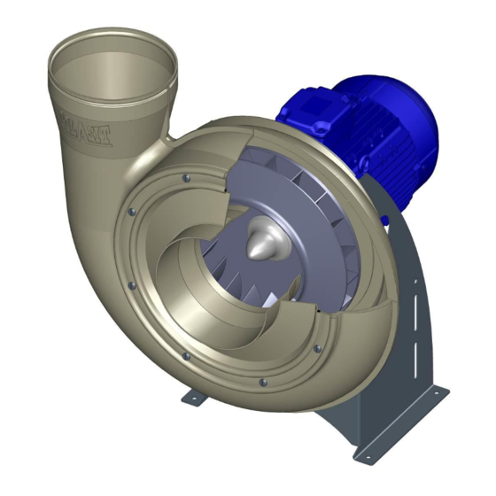
In the centrifugal fan, a gaseous medium is drawn in through the inlet connec- tion in the direction of the motor axis and deflected radially by the rotating im- peller. 26 / 88 Operating instructions CMVpro 125-400 ATEX | Version 1-en... -
Page 27: Signs And Warning Symbols On The Fan
(max. frequency [f ] and other information). The operator's responsibilities regarding these signs on the fan are to • keep them clean and uncovered, • replace them if damaged or missing. Operating instructions CMVpro 125-400 ATEX | Version 1-en 27 / 88... -
Page 28: Options And Accessories
• Designed for permissible fan vibration according to ISO 14694. Fig. 5: Vibration absorbers for ceiling mounting Instructions for vibration absorber selection and item characteristics Chap. 7.4 [} 38]. 28 / 88 Operating instructions CMVpro 125-400 ATEX | Version 1-en... -
Page 29: Sleeves
• Inlet and outlet connections with flange connec- tion. • Executions: See CMVpro accessories on the manufacturer’s website (www.colasit.ch). • Sleeves with flange required Chap. 5.3.3 [} 29]. Fig. 8: Flange connections Operating instructions CMVpro 125-400 ATEX | Version 1-en 29 / 88... -
Page 30: Condensate Drain
Chap. 8.3.3 [} 50]. • FC parameterization Chap. 8.3 [} 47]. • With connection for PTC thermistor tripping de- vice or integrated PTC thermistor monitoring Chap. 8.2.3 [} 46]. Fig. 11: Frequency converter (example) 30 / 88 Operating instructions CMVpro 125-400 ATEX | Version 1-en... -
Page 31: Speed Adjustment Potentiometer
• Made of material that conforms to zone. • Protects electric motor or electric motor with at- tached FC (accessory) from the weather. • For mounting instructions Chap. 8.6 [} 54]. Fig. 14: Motor cover Operating instructions CMVpro 125-400 ATEX | Version 1-en 31 / 88... -
Page 32: Protective Grid
• Use with hazardous, aggressive conveyed media when the fan is operated in an overpressure condi- tion. • Wear part • For mounting instructions, see Chap. 12.9 [} 76]. Fig. 16: Hub seal 32 / 88 Operating instructions CMVpro 125-400 ATEX | Version 1-en... -
Page 33: Transport
Do not receive delivery, or doing so only conditionally. Record transport damage (photos). Note the extent of the damage on the transport paperwork or on the trans- port company’s bill of lading. File a complaint immediately. Operating instructions CMVpro 125-400 ATEX | Version 1-en 33 / 88... -
Page 34: Packing
Fig. 17: Package with lifting eye bolts • Let down and adjust a package that doesn’t hang level: Shorten or lengthen legs on one side appropriately until all legs are loaded equally. 34 / 88 Operating instructions CMVpro 125-400 ATEX | Version 1-en... -
Page 35: Transport By Pallet Stacker Or Forklift
• Forks inserted under the pallet as depicted such that they stick out from the opposite side. Fig. 20: Package on transport pallet Operating instructions CMVpro 125-400 ATEX | Version 1-en 35 / 88... -
Page 36: Mechanical Installation
• Vibration resistant • Flat surface • Suitable for absorption of static and dynamic loads. • For calculations for the mounting parts, assume four times the fan weight. 36 / 88 Operating instructions CMVpro 125-400 ATEX | Version 1-en... -
Page 37: Splinter Protection - Check Proper Mounting
(1) of the cas- ing. • The rubber band lies in notch (2) on the welding edge. • Snap hooks are hooked through the eyelets. Fig. 22: Proper mounting of the splinter protection Operating instructions CMVpro 125-400 ATEX | Version 1-en 37 / 88... -
Page 38: Vibration Absorbers Mounting
M8 x 23 Suitable vibration absorbers for ceiling mounting Fan/ Type for ceiling Connection Load Shore Quantity size mounting thread capacity hardness [pc] [kg/pc] CMVpro 125-200 G-E-06 CMVpro 250-400 G-E-10 38 / 88 Operating instructions CMVpro 125-400 ATEX | Version 1-en... -
Page 39: Foundation Mounting
• Installation location require- ments Chap. 7.2 [} 36]. • Wall bracket shall be de- signed for four times the fan weight. • Fastening elements present. Fig. 24: Fastening recommendation for wall mounting Operating instructions CMVpro 125-400 ATEX | Version 1-en 39 / 88... - Page 40 Fig. 25: Mounting position on the wall bracket Series [mm] CMVpro 125 CMVpro 160 CMVpro 200 CMVpro 250 CMVpro 315 1000 1000 1000 CMVpro 400 1000 1000 1000 1000 1000 40 / 88 Operating instructions CMVpro 125-400 ATEX | Version 1-en...
-
Page 41: Ceiling Mounting
Risk of damage due to lateral forces Cracking of the sleeve. ▪ Sleeves can only minimally compensate for a lateral/radial duct misalign- ment. Align connection tubes precisely. Use supports for supplemental securing of connection tubes. Operating instructions CMVpro 125-400 ATEX | Version 1-en 41 / 88... -
Page 42: Connecting Condensate Drain To Siphon
Environmental damage due to toxic condensate If possible, direct condensate downstream of the siphon back into the process. Collect condensate in the collecting container and dispose of according to regulations. 42 / 88 Operating instructions CMVpro 125-400 ATEX | Version 1-en... -
Page 43: Siphon Calculations And Execution
Required siphon height and installation height Fig. 29: Siphon height and installation height Calculation formula with Legend: SI units: h = min. siphon height [mm] = static fan pressure [Pa] stat H = installation height [mm] Operating instructions CMVpro 125-400 ATEX | Version 1-en 43 / 88... -
Page 44: Final Inspection
Chap. 7.3 [} 37]. • If present in ductwork: • Shut-off dampers for inlet and outlet connections are closed. • Service openings are shut. • Complete ATEX test report Chap. 15.1 [} 82]. 44 / 88 Operating instructions CMVpro 125-400 ATEX | Version 1-en... -
Page 45: Electrical Installation
The isolation switch is only a protective device for disconnecting the fan from electrical power during mounting, maintenance, or repair work and not to turn the fan on and off in the context of operation. The isolation switch Operating instructions CMVpro 125-400 ATEX | Version 1-en 45 / 88... -
Page 46: Motor Protection Switch Installation
When connected to a FC, shutdown should be performed by the "safe stop" safety function. This ensures that no residual voltage is applied to the motor windings and that the electric motor can cool down as quickly as possible. 46 / 88 Operating instructions CMVpro 125-400 ATEX | Version 1-en... -
Page 47: Starting Current Limiter
If a frequency converter (FC) is used, the fan must be equipped with an ex- plosion-proof electric motor (Ex db) if the FC and electric motor are not ATEX certified as a unit. Only install frequency converter in a safe location (control cabinet). Operating instructions CMVpro 125-400 ATEX | Version 1-en 47 / 88... -
Page 48: Frequency Converter (Fc) Installation Options
(IM, PM, EC) can be selected as a drive: • IM ... Standard asynchronous motor/three-phase motor • PM ... Permanent magnet motor • EC ... Brushless DC motor 48 / 88 Operating instructions CMVpro 125-400 ATEX | Version 1-en... - Page 49 • or installed separately (4, customer solution). NOTICE Risk of damaging the frequency converter Do not manipulate the isolation switch when the electric motor is running if con- nection option 4 is used. Operating instructions CMVpro 125-400 ATEX | Version 1-en 49 / 88...
-
Page 50: Frequency Converter (Fc) Parameterization
The FC and motor manufacturers offer support for this. 8.3.3 Connecting the electric motor to a frequency converter (FC) Fig. 30: Connection principle for short motor cable (FC close to fan) 50 / 88 Operating instructions CMVpro 125-400 ATEX | Version 1-en... - Page 51 • Strip the cable end appropriately so that contact can be made with the cable shield. Connect the motor connection cable to the electric motor Chap. 8.5 [} 52]. Operating instructions CMVpro 125-400 ATEX | Version 1-en 51 / 88...
-
Page 52: Making Atex-Compliant Ground Connections
Adequately size the cross section of the motor connection cable, taking into ac- count: • Applicable standards and regulations • Cable lengths • Rated current • Environmental conditions • Type of installation 52 / 88 Operating instructions CMVpro 125-400 ATEX | Version 1-en... - Page 53 The terminal assignment is also located on the inside of the terminal box cover. • Connect the phase conductors (L1, L2, L3) of the motor connection cable to the terminal board in the correct order. Operating instructions CMVpro 125-400 ATEX | Version 1-en 53 / 88...
-
Page 54: Mounting Motor Cover
• Check connections of protective earthing (PE) and grounding for fixed posi- tion and for execution compliant with standards. • If frequency converter (FC) is used: • Check FC terminal assignment, shield connection, and cable strain re- lief. 54 / 88 Operating instructions CMVpro 125-400 ATEX | Version 1-en... - Page 55 V/f characteristic curves, acceleration and braking times Chap. 8.3 [} 47]. If required for control and placement in service, connect an external control unit to the FC. • Complete ATEX test report Chap. 15.1 [} 82]. Operating instructions CMVpro 125-400 ATEX | Version 1-en 55 / 88...
-
Page 56: Placement In Service
• Test start/stop and acceleration behavior starting at a low frequency (25 Hz). • Increase fan speed from minimum to maximum speed Chap. 8.3.2 [} 50] • with an external signal from the higher-level controller, 56 / 88 Operating instructions CMVpro 125-400 ATEX | Version 1-en... -
Page 57: Conduct Test Run
* Establish based on historical limit values. The measured data provides comparison values during maintenance. Heating, ventilation, air conditioning (HVAC), and agriculture: BV-2 < 3.7 kW Industrial processes, etc.: BV-3 > 3.7 kW Operating instructions CMVpro 125-400 ATEX | Version 1-en 57 / 88... - Page 58 • The initial commissioning of the fan must also be documented with an ATEX test report Chap. 15.1 [} 82]. Either deliver the completed ATEX test re- port to the operator or keep it with the project documents. 58 / 88 Operating instructions CMVpro 125-400 ATEX | Version 1-en...
-
Page 59: Operation
• Keep the installation site of the fan clean. Observe cleaning interval and adjust if necessary Chap. 11.2 [} 61]. Operating instructions CMVpro 125-400 ATEX | Version 1-en 59 / 88... -
Page 60: Maintenance
▪ Cleaning of the fan housing, impeller, and plastic parts with a dry cloth leads to electrostatic charge. Only clean the fan with a damp cloth in a potentially explosive atmosphere. 60 / 88 Operating instructions CMVpro 125-400 ATEX | Version 1-en... -
Page 61: Maintenance Table
• For leak tightness: Sleeves, inlet cover, optional hub seal. • For loose screw connections. • Smooth operation of fan: For irregular running, check for vibration or noise Chap. 9.2.3 [} 57]. Operating instructions CMVpro 125-400 ATEX | Version 1-en 61 / 88... -
Page 62: Inside Inspection
The mechanical and electrical functionality of the fan are assessed in the annual inspection, and its continued operation is ensured. This also applies in the event of extensive downtime. Check during outside inspection 62 / 88 Operating instructions CMVpro 125-400 ATEX | Version 1-en... - Page 63 Chap. 7.3 [} 37]. • Fixed position of all screw connections. • Fixed position of all fastening elements (anchors) in the foundation (baseplate). • Short test run, checking for vibration and noise. Operating instructions CMVpro 125-400 ATEX | Version 1-en 63 / 88...
-
Page 64: Repair
Adjust the speed for fan causes high pres- the new conditions sure loss. within the limits of the intended use. Damper valve improp- Adjust the system. erly positioned in duct- work. 64 / 88 Operating instructions CMVpro 125-400 ATEX | Version 1-en... - Page 65 Chap. 8.2.2 [} 46]. tripping device, Check FC parameters. Parameterize FC prop- or FC switches erly. off. Faulty motor connec- Measure current draw. Check motor connec- tion. tion (star/delta) Chap. 8.5 [} 52]. Operating instructions CMVpro 125-400 ATEX | Version 1-en 65 / 88...
- Page 66 Change in length of Chap. 7.8 [} 41]. ductwork due to ther- mal expansion. Loose impeller. Impeller loosened on Check and tighten hub motor shaft? adapter Chap. 12.5 [} 70]. 66 / 88 Operating instructions CMVpro 125-400 ATEX | Version 1-en...
- Page 67 Prohibited op- Ductwork not leak Check for leakage. Seal up. erating condi- tight. tions. Loose hose clamps or Re-tighten hose damaged sleeves. clamps or replace sleeves Chap. 7.8 [} 41]. Operating instructions CMVpro 125-400 ATEX | Version 1-en 67 / 88...
- Page 68 (without ment. tive pressure. peller hub. optional hub seal). Install optional hub seal. Hub seal worn or de- Visual inspection. Replace sealing fective. Chap. 12.9 [} 76]. 68 / 88 Operating instructions CMVpro 125-400 ATEX | Version 1-en...
-
Page 69: Spare Parts And Wear Parts
Hang tag on isolation switch. Shut the shut-off damper to the supply air duct and discharge duct. Drain condensate to condensate drain type K (option). Operating instructions CMVpro 125-400 ATEX | Version 1-en 69 / 88... -
Page 70: Impeller Exchange
Only a leakproof, undam- aged hub cap prevents aggressive con- veyed media from corroding the motor shaft and impeller hub, resulting in de- struction of the impeller. Fig. 36: Removing hub cap 70 / 88 Operating instructions CMVpro 125-400 ATEX | Version 1-en... - Page 71 The impeller may not grind. • Heat new hub cap evenly to approx. 60 °C with hot air blower and press onto hub. Check mounted hub cap for cracks and damage. Operating instructions CMVpro 125-400 ATEX | Version 1-en 71 / 88...
-
Page 72: Casing Exchange
• to the tightening torque specified in the following table. Fan/size Fastener threads Max. tightening torque [Nm] CMVpro 125 CMVpro 160 - 400 • Tighten the grounding cable to the ground connection of the casing Chap. 8.4 [} 52]. 72 / 88 Operating instructions CMVpro 125-400 ATEX | Version 1-en... -
Page 73: Electric Motor Exchange
Observe the instructions in the manual from the motor manufacturer. • Fasten mounting nuts according to the following table. • The thread is based on the motor size. Thread Max. tightening torque [Nm] Operating instructions CMVpro 125-400 ATEX | Version 1-en 73 / 88... -
Page 74: Check Impeller
Instead, the distance X from the inlet connection to the impeller support disc is measured according to the table below. As an aid, place a wooden board (1, see illustration) across the inlet connection. 74 / 88 Operating instructions CMVpro 125-400 ATEX | Version 1-en... - Page 75 Check impeller mobility. Press new hub cap onto hub. Assemble fan. Conduct test run Chap. 9.2.3 [} 57]. For necessary removal and mounting work, see Chap. 12.5 [} 70] for mount- ing instructions. Operating instructions CMVpro 125-400 ATEX | Version 1-en 75 / 88...
-
Page 76: Hub Seal (Option) Replacement
Insert new hub seal in seal casing. • Order the hub seal as a wear part in a timely manner. Assemble fan Chap. 12.5 [} 70], mount- ing instructions. Fig. 41: Inserting hub seal 76 / 88 Operating instructions CMVpro 125-400 ATEX | Version 1-en... -
Page 77: Removal From Service, Disposal, And Recycling
Risk of eye irritation, cough, difficulty breathing, burn, and suffocation. Wear protective equipment. Close shut-off damper to inlet and outlet connections. Watch for deposits and condensate of the conveyed medium in the fan and ductwork. Operating instructions CMVpro 125-400 ATEX | Version 1-en 77 / 88... -
Page 78: Disposal Instructions
• Separate the fan components into material groups and dispose of them sep- arately: • Metals • Plastics • Electrical components Dispose of plastic parts contaminated by conveyed media that are harmful to health and the environment as special waste. 78 / 88 Operating instructions CMVpro 125-400 ATEX | Version 1-en... -
Page 79: Eu - Declaration Of Conformity
EN ISO 80079-37: 2016 EN 14986: 2017 Name and address of the Andreas Roth document manager COLASIT AG Faulenbachweg 63 3700 Spiez Switzerland Spiez, 6/7/2021 U. Moser (Division manager) Operating instructions CMVpro 125-400 ATEX | Version 1-en 79 / 88... -
Page 80: Atex - Declaration Of Conformity
(7) The design of this equipment and the various executions are specified in the ap- pendix to this Declaration of Conformity and in the technical report. (8) Colasit AG certifies compliance with the essential health and safety require- ments for the design and construction of equipment and protective systems in- tended for use in potentially explosive atmospheres according to Annex II of Di- rective 2014/34/EU. - Page 81 • Conveyed media are chemically aggressive gases, vapors, or air contami- nated with them. • Material selection depends on the requirements (zone inside/outside) and the presence of droplets. (16) Test report TD-000 823 Operating instructions CMVpro 125-400 ATEX | Version 1-en 81 / 88...
-
Page 82: Atex Test Report
• For ongoing operation, it is recommended to keep a machine logbook in which the explosion protection testing is also entered. Templates for the ATEX test report and machine logbook can be obtained from the point of contact. 82 / 88 Operating instructions CMVpro 125-400 ATEX | Version 1-en... -
Page 83: Index
Degree of protection 32 Health protection 14 Direction of rotation arrow 56 Hoisting gear 33, 34, 73 Disposable packing 34 Hole pattern 39, 41 Disposal 7, 15, 77, 78 Operating instructions CMVpro 125-400 ATEX | Version 1-en 83 / 88... - Page 84 Material damage 7, 9, 12, 17, 33, 36, 38, Production downtime 36, 38, 62, 69 56, 62, 69 Protective devices 54, 60 Minimum distance 21, 37, 65 Protective earthing 54 84 / 88 Operating instructions CMVpro 125-400 ATEX | Version 1-en...
- Page 85 39, 40, 41 Supply air duct 56, 60, 69 Support 21, 26, 35, 36, 39, 45, 49, 54, 61, 63, 72, 77, 78 Support braces 40 Supports 41 Swinging movements 33 Operating instructions CMVpro 125-400 ATEX | Version 1-en 85 / 88...
- Page 86 Notes Notes 86 / 88 Operating instructions CMVpro 125-400 ATEX | Version 1-en...
- Page 87 Notes Operating instructions CMVpro 125-400 ATEX | Version 1-en 87 / 88...
- Page 88 - since 1945 - When it comes to thermoplastics, Colasit AG is one of the world's leading brands in fan and system engineering. Our qualified staff impress with technical expertise and great dedication, guaranteeing you the highest quality on all five continents.
Need help?
Do you have a question about the CMVpro 125-400 ATEX and is the answer not in the manual?
Questions and answers