
Subscribe to Our Youtube Channel
Related Manuals for Colasit CMVpro 125


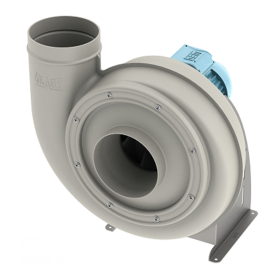
Summary of Contents for Colasit CMVpro 125
- Page 1 Operating instructions CMVpro 125-400 Centrifugal fan Your point of contact: Colasit Representative Street Location Version 1-en | 06/2021...
- Page 2 Description Date Name 1-en First version published. 6/10/2021 A. Roth Document identification Translation of the original German operating instructions. Colasit TD-000826 Contact information Manufacturer COLASIT AG Faulenbachweg 63 CH-3700 Spiez E-mail: info@colasit.ch Phone: +41 (0)33 655 61 61 Importer Name...
-
Page 3: Table Of Contents
Signs and warning symbols on the fan..............Options and accessories ..................4.3.1 Vibration absorbers..................4.3.2 Sleeves ...................... 4.3.3 Sleeves with flange ..................4.3.4 Flange connections..................4.3.5 Condensate drain..................4.3.6 Isolation switch................... 4.3.7 Frequency converter (FC)................Operating instructions CMVpro 125-400 | Version 1-en 3 / 76... - Page 4 7.3.2 Frequency converter (FC) parameterization ..........7.3.3 Connecting the electric motor to a frequency converter (FC) ....Connecting the electric motor................. Mounting motor cover..................... Final inspection....................... Placement in service .................... 4 / 76 Operating instructions CMVpro 125-400 | Version 1-en...
- Page 5 Removal from service, disposal, and recycling ..........12.1 Safety instructions ....................12.2 Environmental protection..................12.3 Removal from service..................... 12.4 Disposal instructions....................EU - Declaration of conformity................Index ........................Machine logbook ....................Operating instructions CMVpro 125-400 | Version 1-en 5 / 76...
-
Page 6: Operating Instruction Information
For the sake of simplification, in these operating instructions, • the company Colasit AG is referred to as the “manufacturer,” • the CMVpro 125-400 centrifugal fan is referred to as the “fan,” • “frequency converter” is abbreviated as “FC,” • chapter and page number references appear as follows: Chap. -
Page 7: Copyright
The use and distribution of the operating instructions is permitted in the context of using the fan. Any other use is only permitted with the written consent of the manufacturer. Operating instructions CMVpro 125-400 | Version 1-en 7 / 76... -
Page 8: Additional Safety Instructions
• For independent assessment, the operator is to consult the pertinent available resistance lists for plastics. The SIMCHEM guide is found on the manufacturer's website (www.colasit.ch). 8 / 76 Operating instructions CMVpro 125-400 | Version 1-en... - Page 9 • The operating point (see diagram on the technical data sheet) shall be above the minimum permissible conveyed volume. • So that no or minimal conveyed medium escapes from the impeller hub, Operating instructions CMVpro 125-400 | Version 1-en 9 / 76...
-
Page 10: Reasonably Foreseeable Misuse
Imbalance and vibration caused by deposits damage the motor bear- ings and impeller. • Use of non-original spare parts. • Unauthorized modifications or alterations to the fan without the written con- sent of the manufacturer. 10 / 76 Operating instructions CMVpro 125-400 | Version 1-en... -
Page 11: Equipment Limits
The fan is designed and manufactured in accordance with the state of the art and the recognized technical safety regulations. Residual risks nevertheless re- main. They are indicated by safety instructions in these operating instructions and require the user to proceed with caution. Operating instructions CMVpro 125-400 | Version 1-en 11 / 76... -
Page 12: Target Groups And Personnel Requirements
• Ensure that the fan is always in a technically sound condition under obser- vance of the maintenance intervals per these operating instructions. • Initiate and verify that the function and integrity of all fan safeguards are checked regularly. 12 / 76 Operating instructions CMVpro 125-400 | Version 1-en... -
Page 13: Transport Personnel
• All work on the fan’s electrical components may only be carried out by elec- tricians. • The fan may only be connected to the frequency converter by an electrician • after its operating instructions have been read and understood, Operating instructions CMVpro 125-400 | Version 1-en 13 / 76... -
Page 14: Operating Personnel
• The same requirements apply as for the mounting personnel Chap. 2.3.3 [} 13]. • An electrician is responsible for carrying out maintenance and repair work and for switching off and safely disconnecting the power supply from the fan. 14 / 76 Operating instructions CMVpro 125-400 | Version 1-en... -
Page 15: Essential Safety Instructions
▪ Conditions for prevention of the danger... Measures for prevention of the danger... This warning instruction informs of a dangerous situation that can damage the fan or or lead to other material damage. Operating instructions CMVpro 125-400 | Version 1-en 15 / 76... -
Page 16: Personal Protective Equipment
Work gloves for protection from injuries, burns, or contact with ag- gressive, toxic residues of the conveyed medium. Safety shoes for protection from crushing and from falling parts as well as slips and falls on slick surfaces. 16 / 76 Operating instructions CMVpro 125-400 | Version 1-en... -
Page 17: Mechanical Hazards
Establish an electrically safe work condition before beginning work. Promptly rectify any defects discovered in the electrical components and wiring of the fan. Eliminate moisture from current-carrying components to avoid a short cir- cuit. Operating instructions CMVpro 125-400 | Version 1-en 17 / 76... -
Page 18: Danger Due To Electromagnetic Interferences
Wear protective gloves when working on the fan or electric motor. When mounting the fan, observe the minimum distance between the fan cowl of the electric motor and neighboring components or walls Chap. 6.2 [} 30]. 18 / 76 Operating instructions CMVpro 125-400 | Version 1-en... -
Page 19: Noise Hazard
Actions to take in an emergency Explosion or melting of the plastic components during fan operation constitutes an emergency situation. Possible causes (due to use in a manner other than intended): Operating instructions CMVpro 125-400 | Version 1-en 19 / 76... - Page 20 Do not attempt to extinguish in confined, small, or enclosed spaces. Instead, fight fire from outside through open door. Do not access area where fire occurred until it has been thoroughly venti- lated. 20 / 76 Operating instructions CMVpro 125-400 | Version 1-en...
-
Page 21: Structure And Function
In the centrifugal fan, a gaseous medium is drawn in through the inlet connec- tion in the direction of the motor axis and deflected radially by the rotating im- peller. Operating instructions CMVpro 125-400 | Version 1-en 21 / 76... -
Page 22: Signs And Warning Symbols On The Fan
Chap. 6.6 [} 33]. • Dampens vibration and pre- vents operating faults. • Designed for permissible fan vibration according to ISO 14694. Fig. 4: Vibration absorbers for floor and wall mounting 22 / 76 Operating instructions CMVpro 125-400 | Version 1-en... -
Page 23: Sleeves
• For flexible connection of the inlet and outlet connections to ductwork with flange connec- tions. • Executions: See accessories for the CMVpro 125 - 400 on the manufacturer’s website (www.colasit.ch). Fig. 7: Sleeves with flange Operating instructions CMVpro 125-400 | Version 1-en 23 / 76... -
Page 24: Flange Connections
• Can be locked in the OFF position with a cus- tomer-supplied padlock. Note: The isolation switch is also referred to as a maintenance switch. Fig. 10: Isolation switch 24 / 76 Operating instructions CMVpro 125-400 | Version 1-en... -
Page 25: Frequency Converter (Fc)
• Required accessory for wall mounting. • Executions: See accessories for the CMVpro 125 - 400 on the manufacturer’s website (www.colasit.ch). • For mounting instructions Chap. 6.6 [} 33]. Fig. 13: Wall bracket Operating instructions CMVpro 125-400 | Version 1-en 25 / 76... -
Page 26: Motor Cover
• Use with hazardous, aggressive conveyed media when the fan is operated in an overpressure condi- tion. • Wear part • For mounting instructions, see Chap. 11.9 [} 66]. Fig. 16: Hub seal 26 / 76 Operating instructions CMVpro 125-400 | Version 1-en... -
Page 27: Transport
Do not receive delivery, or doing so only conditionally. Record transport damage (photos). Note the extent of the damage on the transport paperwork or on the trans- port company’s bill of lading. File a complaint immediately. Operating instructions CMVpro 125-400 | Version 1-en 27 / 76... -
Page 28: Packing
Fig. 17: Package with lifting eye bolts • Let down and adjust a package that doesn’t hang level: Shorten or lengthen legs on one side appropriately until all legs are loaded equally. 28 / 76 Operating instructions CMVpro 125-400 | Version 1-en... -
Page 29: Transport By Pallet Stacker Or Forklift
A package on a pallet can be transported by pallet stacker or forklift under the following conditions: • Forks inserted under the pallet as depicted such that they stick out from the opposite side. Fig. 20: Package on transport pallet Operating instructions CMVpro 125-400 | Version 1-en 29 / 76... -
Page 30: Mechanical Installation
Foundation (baseplate) or mounting surface shall meet the following require- ments: • Vibration resistant • Flat surface • Suitable for absorption of static and dynamic loads. • For calculations for the mounting parts, assume four times the fan weight. 30 / 76 Operating instructions CMVpro 125-400 | Version 1-en... -
Page 31: Splinter Protection - Check Proper Mounting
(1) of the cas- ing. • The rubber band lies in notch (2) on the welding edge. • Snap hooks are hooked through the eyelets. Fig. 22: Proper mounting of the splinter protection Operating instructions CMVpro 125-400 | Version 1-en 31 / 76... -
Page 32: Vibration Absorbers Mounting
M8 x 23 Suitable vibration absorbers for ceiling mounting Fan/ Type for ceiling Connection Load Shore Quantity size mounting thread capacity hardness [pc] [kg/pc] CMVpro 125-200 G-E-06 CMVpro 250-400 G-E-10 32 / 76 Operating instructions CMVpro 125-400 | Version 1-en... -
Page 33: Foundation Mounting
• Installation location require- ments Chap. 6.2 [} 30]. • Wall bracket shall be de- signed for four times the fan weight. • Fastening elements present. Fig. 24: Fastening recommendation for wall mounting Operating instructions CMVpro 125-400 | Version 1-en 33 / 76... - Page 34 Fig. 25: Mounting position on the wall bracket Series [mm] CMVpro 125 CMVpro 160 CMVpro 200 CMVpro 250 CMVpro 315 1000 1000 1000 CMVpro 400 1000 1000 1000 1000 1000 34 / 76 Operating instructions CMVpro 125-400 | Version 1-en...
-
Page 35: Ceiling Mounting
Risk of damage due to lateral forces Cracking of the sleeve. ▪ Sleeves can only minimally compensate for a lateral/radial duct misalign- ment. Align connection ducts precisely. Use supports for supplemental securing of connection ducts. Operating instructions CMVpro 125-400 | Version 1-en 35 / 76... -
Page 36: Connecting Condensate Drain To Siphon
Environmental damage due to toxic condensate If possible, direct condensate downstream of the siphon back into the process. Collect condensate in the collecting container and dispose of according to regulations. 36 / 76 Operating instructions CMVpro 125-400 | Version 1-en... -
Page 37: Siphon Calculations And Execution
Required siphon height and installation height Fig. 29: Siphon height and installation height Calculation formula with Legend: SI-units: h = min. siphon height [mm] = static fan pressure [Pa] stat H = installation height [mm] Operating instructions CMVpro 125-400 | Version 1-en 37 / 76... -
Page 38: Final Inspection
(baseplate) or mounting surface are tight. • Inspect splinter protection Chap. 6.3 [} 31]. • If present in ductwork: • Shut-off dampers for inlet and outlet connections are closed. • Service openings are shut. 38 / 76 Operating instructions CMVpro 125-400 | Version 1-en... -
Page 39: Electrical Installation
The isolation switch • is a required protective device, • shall be installed in an easily-accessible location near the fan, Operating instructions CMVpro 125-400 | Version 1-en 39 / 76... -
Page 40: Motor Protection Switch Installation
• Star-delta start-up • Soft start/soft starter • FC with current-limiting and start-up characteristics. Observe the national regulations and limit values of the power system operator for direct start-up of three-phase motors. 40 / 76 Operating instructions CMVpro 125-400 | Version 1-en... -
Page 41: Instructions For Frequency Converter (Fc) Use
7.3.1 Frequency converter (FC) installation options For CMVpro 125-400 type centrifugal fans, different executions of electric mo- tors (IM, EC, PM) can be selected as a drive: • IM ... Standard asynchronous motor/three-phase motor •... - Page 42 • or installed separately in the control cabinet (4, customer solution). NOTICE Risk of damaging the frequency converter Do not manipulate the isolation switch when the electric motor is running if con- nection option 4 is used. 42 / 76 Operating instructions CMVpro 125-400 | Version 1-en...
-
Page 43: Frequency Converter (Fc) Parameterization
Observe the fan manufacturer’s EMC guide. Comply with the instructions in the FC operating instructions. Observe the max- imum permissible length of the motor connection cable between FC and electric motor. Operating instructions CMVpro 125-400 | Version 1-en 43 / 76... -
Page 44: Connecting The Electric Motor
When running the cable, observe the following essential principles: • Avoid damaging the cable by pinching, cutting, pulling, etc. during installa- tion. 44 / 76 Operating instructions CMVpro 125-400 | Version 1-en... - Page 45 • Check: • Cable gland on the terminal box is suitable for the diameter of the con- nection cable. Operating instructions CMVpro 125-400 | Version 1-en 45 / 76...
-
Page 46: Mounting Motor Cover
• Check and record important FC parameters and settings: Maximum output frequency, V/f characteristic curves, acceleration and braking times Chap. 7.3 [} 41]. If required for control and placement in service, connect an external control unit to the FC. 46 / 76 Operating instructions CMVpro 125-400 | Version 1-en... -
Page 47: Placement In Service
• Test start/stop and acceleration behavior starting at a low frequency (25 Hz). • Increase fan speed from minimum to maximum speed Chap. 7.3.2 [} 43] • with an external signal from the higher-level controller, Operating instructions CMVpro 125-400 | Version 1-en 47 / 76... -
Page 48: Conduct Test Run
* Establish based on historical limit values. The measured data provides comparison values during maintenance. Category BV-2 applies to heating, ventilation, air conditioning (HVAC), and agri- culture. Category BV-3 applies to industrial processes and power generation. 48 / 76 Operating instructions CMVpro 125-400 | Version 1-en... - Page 49 • During initial commissioning, prepare a test report in accordance with EN 60204-1 or a corresponding national standard and deliver it to the operator. Operating instructions CMVpro 125-400 | Version 1-en 49 / 76...
-
Page 50: Operation
• Keep the installation site of the fan clean. Observe cleaning interval and adjust if necessary Chap. 10.2 [} 51]. 50 / 76 Operating instructions CMVpro 125-400 | Version 1-en... -
Page 51: Maintenance
10.2 Maintenance table The maintenance intervals (W/weekly, M/monthly, 6M/semi-annually and 12M/ annually) are to be adapted to the current operating conditions of the fan as de- termined by the customer. Operating instructions CMVpro 125-400 | Version 1-en 51 / 76... -
Page 52: Maintenance Work
• Smooth operation of fan: For irregular running, check for vibration or noise Chap. 8.2.3 [} 48]. • Check electric motor for possible overheating (overloading). CAUTION Risk of burn Promptly report any defects found and have them properly rectified. 52 / 76 Operating instructions CMVpro 125-400 | Version 1-en... -
Page 53: Inside Inspection
This also applies in the event of extensive downtime. Outside inspection • For stress cracks: fan housing • For cracking: vibration absorbers • For noises: motor bearings Operating instructions CMVpro 125-400 | Version 1-en 53 / 76... - Page 54 Chap. 6.3 [} 31]. • All screw connections are tight. • Fixed position of all fastening elements (anchors) in the foundation (baseplate). • Short test run, checking for vibration and noise. 54 / 76 Operating instructions CMVpro 125-400 | Version 1-en...
-
Page 55: Repair
(L > 3 x duct Ø). Operating Faulty motor winding. Winding measure- Replace electric motor speed cannot ment. Chap. 11.7 [} 64]. be reached. Operating instructions CMVpro 125-400 | Version 1-en 55 / 76... - Page 56 Faulty motor connec- Measure current draw. Check motor connec- tion. tion (star/delta) Chap. 7.4 [} 44]. Impeller blocked or Visual inspection. Remove deposits or stopped. foreign objects Chap. 10.3.3 [} 53]. 56 / 76 Operating instructions CMVpro 125-400 | Version 1-en...
- Page 57 Chap. 11.8 [} 65] Clamp down clamping adapter Chap. 11.5 [} 61]. Impeller dips into con- Type K: visual inspec- Drain condensate densate at bottom of tion. Chap. 4.3.5 [} 24]. casing. Operating instructions CMVpro 125-400 | Version 1-en 57 / 76...
- Page 58 Chap. 7.3.2 [} 43]. cording to characteris- erly (speed too high, tic map in technical Observe different con- overheating of electric data sheet. figuration for PM mo- motor). tors. 58 / 76 Operating instructions CMVpro 125-400 | Version 1-en...
- Page 59 (without ment. tive pressure. peller hub. optional hub seal). Install optional hub seal. Hub seal worn or de- Visual inspection. Replace sealing fective. Chap. 11.9 [} 66]. Operating instructions CMVpro 125-400 | Version 1-en 59 / 76...
-
Page 60: Spare Parts And Wear Parts
Hang tag on isolation switch. Shut the shut-off damper to the supply air duct and discharge duct. Drain condensate to condensate drain type K (option). 60 / 76 Operating instructions CMVpro 125-400 | Version 1-en... -
Page 61: Impeller Exchange
• Cut out and remove hub cap with appropriate tools. • The hub cap cannot be removed non-destruc- tively - order spare part in a timely manner. Fig. 35: Removing hub cap Operating instructions CMVpro 125-400 | Version 1-en 61 / 76... - Page 62 Fig. 36: Removing impeller The impeller is mounted directly to the motor shaft on fans CMVpro 125-200 with electric motors of size 100 or 112 as well as for CMVpro 250-400 with elec- tric motors of size 132.
-
Page 63: Casing Exchange
• with wedge-lock washers (Nord-Lock, see detail) ) (mandatory require- ment). Do not use threadlocker (Loctite)! • to the tightening torque specified in the following table. Fan/size Fastener threads Max. tightening torque [Nm] CMVpro 125 CMVpro 160 - 400 Operating instructions CMVpro 125-400 | Version 1-en 63 / 76... -
Page 64: Electric Motor Exchange
• The thread is based on the motor size. Thread Max. tightening torque [Nm] • Connect electric motor Chap. 7.4 [} 44] • Check motor rotation direction Chap. 8.2.1 [} 47]. • Conduct test run Chap. 8.2.3 [} 48]. 64 / 76 Operating instructions CMVpro 125-400 | Version 1-en... -
Page 65: Measuring And Setting Impeller Position
CMVpro 315 CMVpro 400 Procedure: Prepare fan for measurement: • Loosen sleeve at the inlet connection. • Remove ductwork end at the inlet connection. Conduct measurement according to figure 39. Operating instructions CMVpro 125-400 | Version 1-en 65 / 76... -
Page 66: Hub Seal (Option) Replacement
Insert new hub seal in seal casing. • Order the hub seal as a wear part in a timely manner. Assemble fan Chap. 11.5 [} 61], mount- ing instructions. Fig. 40: Inserting hub seal 66 / 76 Operating instructions CMVpro 125-400 | Version 1-en... -
Page 67: Removal From Service, Disposal, And Recycling
In the event that the fan contains PVC plastic materials, deliver the following in- formation to the waste disposal company: Raw material: Extruded PVC-U sheet SCIP Reference Number: 788557b9-946b-4400-b46e-1a50ed8ee392 Hazardous Material: Dioctyltin compounds (DOTE) Operating instructions CMVpro 125-400 | Version 1-en 67 / 76... -
Page 68: Removal From Service
When disposing of the fan, observe all nationally applicable regulations and le- gal requirements for waste disposal, and comply with regional environmental protection regulations. Preferably, commission a waste disposal company for proper recycling or dis- posal. 68 / 76 Operating instructions CMVpro 125-400 | Version 1-en... - Page 69 • Separate the fan components into material groups and dispose of them sep- arately: • Metals • Plastics • Electrical components Dispose of plastic parts contaminated by conveyed media that are harmful to health and the environment as special waste. Operating instructions CMVpro 125-400 | Version 1-en 69 / 76...
-
Page 70: Eu - Declaration Of Conformity
EN ISO 12499: 2008 EN 60204-1: 2019 EN IEC 61000-6-4:2019 Name and address of the Andreas Roth document manager COLASIT AG Faulenbachweg 63 3700 Spiez Switzerland Spiez, 6/7/2021 U. Moser (Division manager) 70 / 76 Operating instructions CMVpro 125-400 | Version 1-en... -
Page 71: Index
Direction of rotation arrow 47 Hole pattern 33, 35 Disposable packing 28 Hose clamps 23, 36, 58 Disposal 6, 13, 67, 68 Hub cap 21, 61, 62, 66 Disposal instructions 28, 68 Operating instructions CMVpro 125-400 | Version 1-en 71 / 76... - Page 72 45, 46 Minimum distance 18, 31, 55 Protective equipment 12, 13, 16, 17, 19, Misuse 10 27, 30, 51, 68 Motor 10, 32, 56 Protective grid 10, 19, 26, 52, 54 72 / 76 Operating instructions CMVpro 125-400 | Version 1-en...
- Page 73 Supply air duct 47, 51, 60 Support 18, 21, 29, 30, 33, 35, 39, 42, 46, 52, 54, 63, 68 Support braces 34 Swinging movements 27 Terminal 11 Terms and conditions 28 Operating instructions CMVpro 125-400 | Version 1-en 73 / 76...
-
Page 74: Machine Logbook
• Special events (process changes, power outage, etc.). • Change of responsible maintenance personnel. Classify the activities with abbreviations: I - Inspection, M - Maintenance, R - Repair Date Name I/M/R Description/Notes 74 / 76 Operating instructions CMVpro 125-400 | Version 1-en... - Page 75 Notes Notes Operating instructions CMVpro 125-400 | Version 1-en 75 / 76...
- Page 76 - since 1945 - When it comes to thermoplastics, Colasit AG is one of the world's leading brands in fan and system engineering. Our qualified staff impress with technical expertise and great dedication, guaranteeing you the highest quality on all five continents.
Need help?
Do you have a question about the CMVpro 125 and is the answer not in the manual?
Questions and answers