Table of Contents
Advertisement
Quick Links
Advertisement
Table of Contents

Subscribe to Our Youtube Channel
Related Manuals for Viessmann SDIO/SM1A


Summary of Contents for Viessmann SDIO/SM1A
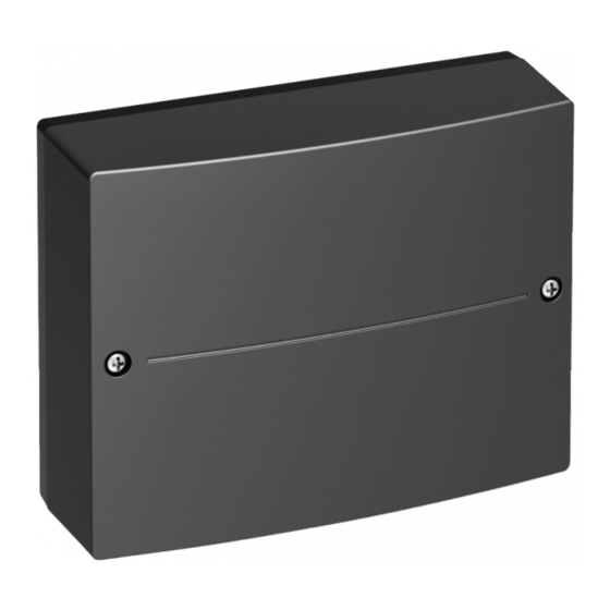
- Page 1 VIESMANN Installation and service instructions for contractors SDIO/SM1A electronics module In conjunction with the Vitotronic control unit and HMU control unit ■ ■ For controlling and regulating a solar DHW heating system SDIO/SM1A electronics module Please keep safe. 5838676 GB...
- Page 2 Never touch hot surfaces on the boiler, burner, lidate our warranty. ■ flue system or pipework. For replacements, use only original spare parts supplied or approved by Viessmann. Please note Electronic assemblies can be damaged by elec- trostatic discharge. Prior to commencing work, touch earthed objects such as heating or water pipes to dis- charge static loads.
- Page 3 Safety instructions Safety instructions (cont.) Safety instructions for operating the system If you smell gas Flue systems and combustion air Danger Ensure that flue systems are clear and cannot be Escaping gas can lead to explosions which may sealed, for instance due to accumulation of conden- result in serious injury.
-
Page 4: Table Of Contents
External heat exchanger ..............26 ■ Cylinder priority control ............... 26 ■ Cyclical heating .................. 27 ■ Version with SDIO/SM1A electronics module and PlusBus ....27 Solar DHW heating ................27 ■ Relay kick ....................28 7. Specification Specification ..................29 Connection and wiring diagram ............. - Page 5 Information Disposal of packaging Please dispose of packaging waste in line with statu- tory regulations. Symbols The steps in connection with commissioning, inspec- Symbol Meaning tion and maintenance are found in the "Commission- Reference to other document containing ing, inspection and maintenance" section and identified further information as follows: Step in a diagram:...
- Page 6 Information System examples For available system examples, see www.viessmann- schemes.com...
- Page 7 230 V∼ 50 Hz 10 kΩ 20 kΩ 10 kΩ 10 kΩ Fig. 1 SDIO/SM1A electronics module Solar circuit pump Cylinder temperature sensor NTC 10 k (stand- Power supply Ω fÖ ard delivery) PlusBus for connecting with HMU control unit,...
- Page 8 III (3 mm) for full isolation. The isolator Observe max. connected load of all accessories must be fitted in the permanent electrical installation, (400 W). If required, connect the SDIO/SM1A elec- in line with installation requirements. We additionally recommend installing an AC/DC- tronics module directly to the mains supply: See ■...
- Page 9 The LED on the top left of the PCB flashes for 1 minute. After 1 minute, the LED lights up permanently. The SDIO/SM1A electronics module is now reset to the factory setting. Adjusting the codes/parameters The codes/parameters for the SDIO/SM1A electronics 4.
- Page 10 Commissioning Configuring the SDIO/SM1A electronics module (cont.) Note Parameter values in bold are factory settings. 00 Start temperature differential, solar circuit pump Display Value Explanations 00:8 ... K 00:2 to 00:30 01 Stop temperature differential, solar circuit pump Display Value...
- Page 11 None 0A:0 Stagnation time reduction not active 0A:5 ... K 0A:1 to 0A:40 0B Frost protection function for solar circuit Display Value Explanations 0B:0 0B:1 Not required in conjunction with Viessmann heat transfer medium...
- Page 12 Commissioning Configuring the SDIO/SM1A electronics module (cont.) 0C Delta T monitoring Display Value Explanations 0C:0 0C:1 No flow rate captured in the solar circuit, or flow rate too low. 0D Night DHW circulation monitoring Display Value Explanations 0D:0 0D:1 Unintentional flow rate in the solar circuit (e.g. at night) is captured.
- Page 13 Commissioning Configuring the SDIO/SM1A electronics module (cont.) 12 Minimum collector temperature Display Value Explanations None 12:0 Minimum temperature limit disabled 10 °C 12:10 Minimum start temperature for solar circuit pump 10 °C ... °C 12:1 to 12:90 20 Extended control function...
- Page 14 Commissioning Configuring the SDIO/SM1A electronics module (cont.) 24 Start temperature for thermostat function Display Value Explanations Parameter "20:5" or "20:6" must be set. 40 °C 24:40 ... °C 24:0 to 24:100 25 Stop temperature for thermostat function Display Value Explanations Parameter "20:5"...
-
Page 15: Faults Displayed With A Fault Code
Carrying out a relay/actuator test. Output not switched or per- Incorrect function configured Check setting of coding address "20". manently switched. SDIO/SM1A electronics mod- Check connection of output (see page 16). ule fault Carrying out a relay/actuator test. Solar control unit switched off MCB F1 has responded. -
Page 16: Check Solar Circuit Pump At Output Sf
∼ Output faulty 230 V . The pump speed is governed by means of a – Replace the SDIO/SM1A electronics module. control signal via PWM connection. – Solar circuit pump faulty Code/parameter "02:2" must be set. Replace solar circuit pump. -
Page 17: Incorrect Circulation In The Solar Circuit
Troubleshooting Repairs (cont.) Temperature in °C Fig. 3 Collector temperature sensor & (sensor type: NTC 20 k Ω ■ Cylinder temperature sensor Temperature sensor ■ ■ Temperature sensor aÖ (sensor type: NTC 10 k Ω Incorrect circulation in the solar circuit If code/parameter "0D:1"... - Page 18 Troubleshooting Repairs (cont.)
-
Page 19: Parts List
Parts lists Parts list The following details are required when ordering parts: ■ Serial no. (see type plate) ■ Position number of the individual part within the assembly (from this parts list) - Page 20 Parts lists Parts list (cont.) 0001 0012 0003 0011 0004 0010 0005 0006 0009 0007 0008 Fig. 4...
- Page 21 Parts lists Parts list (cont.) Pos. Part 0001 SDIO/SM1A electronics module 0002 Plastic parts of casing module 0003 Fuse, 2.0 A (slow) 250 V (10 pce) 0004 Strain relief fittings 0005 Collector temperature sensor NTC 20 k Ω 0006 Power cable no. 40...
-
Page 22: Version With Sm1 And Km-Bus
Function description Version with SM1 and KM-BUS Function description when using the SDIO/SM1A elec- tronics module in conjunction with PlusBus (plug see page 27. Solar DHW heating The solar circuit pump starts according to the following ■ The maximum collector temperature set in coding criteria, resulting in the DHW being heated. -
Page 23: Suppression Of Dhw Cylinder Reheating By The Heat Generator
Function description Version with SM1 and KM-BUS (cont.) Suppression of DHW cylinder reheating by the heat generator In systems with boilers In systems with heat pumps Reheating is suppressed in 2 stages: During solar DHW heating, the "Set DHW tempera- ■... -
Page 24: Reduction Of Stagnation Time
Differential from collector and cylinder temperature In the delivered condition, coding address "0E" is set ■ ■ Flow rate to a value of "1" (operation with Viessmann heat trans- ■ Type of heat transfer medium fer medium). ■ Runtime of solar circuit pump... -
Page 25: Interval Function
Collector frost protection Viessmann collectors are filled with Viessmann heat To prevent damage to the collectors, the solar circuit transfer medium. Consequently, this function does not pump is switched on if the collector temperature falls need to be enabled. -
Page 26: Differential Temperature Control For Central Heating Backup
Function description Version with SM1 and KM-BUS (cont.) Differential temperature control for central heating backup Set code/parameter "20:4". If the following conditions are met, output is 'live': ■ There is a heat demand from one of the connected heating circuits. The temperature captured by temperature sensor ■... -
Page 27: Cyclical Heating
"28". Version with SDIO/SM1A electronics module and PlusBus Solar DHW heating Note Suppression of DHW cylinder reheating by the... -
Page 28: Relay Kick
≙ parameter 950.0. 1 step 0.1 l/h. In the delivered condition, parameter 1136.3 is set to a value of 1 (operation with Viessmann heat transfer medium). Relay kick To prevent the pumps and valves from seizing up they are started for about 10 s every 24 h. -
Page 29: Specification
Specification Specification Rated voltage 230 V∼ Rated frequency 50 Hz Rated current Power consumption – electronics 1.5 W Power consumption 7 mA Protection class IP rating IP 20D to EN 60 529, ensure through design/ installation. Permissible ambient temperature Operation 0 to +40 °C ■... - Page 30 Specification Connection and wiring diagram (cont.) PlusBus for connecting with HMU control unit, DIO electronics module or ADIO electronics module KM-BUS to Vitotronic boiler control unit...
-
Page 31: Final Decommissioning And Disposal
Disposal Final decommissioning and disposal Viessmann products can be recycled. Components For decommissioning the system, isolate the system and substances from the system are not part of ordi- from the power supply and allow components to cool nary household waste. - Page 32 Declaration of Conformity Declaration of Conformity We, Viessmann Werke GmbH & Co. KG, D-35107 Allendorf, declare as sole responsible body that the named product complies with the European directives and supplementary national requirements in terms of its design and operational characteristics.
- Page 33 Specification...............29 Flow rate monitoring...........24 Stagnation time reduction.......... 27 Frost protection............ 25, 28 Suppression of reheating........23, 27 Function description with SDIO/SM1A electronics mod- System examples............6 ule and PlusBus............27 Function description with SM1 and KM-BUS..... 22 Functions, setting............9 Temperature sensors..........16 Thermostat function...........
- Page 36 Viessmann Werke GmbH & Co. KG Viessmann Limited D-35107 Allendorf Hortonwood 30, Telford Telephone: +49 6452 70-0 Shropshire, TF1 7YP, GB Fax: +49 6452 70-2780 Telephone: +44 1952 675000 www.viessmann.com Fax: +44 1952 675040 E-mail: info-uk@viessmann.com...
Need help?
Do you have a question about the SDIO/SM1A and is the answer not in the manual?
Questions and answers