Viessmann Vitosolic 100 Installation And Service Instructions Manual
Hide thumbs
Also See for Vitosolic 100:
- Installation and service instructions manual (72 pages) ,
- Installation and service instructions for contractors (36 pages) ,
- Operating instructions for the system user (13 pages)
Table of Contents
Advertisement
Quick Links
Advertisement
Table of Contents

Related Manuals for Viessmann Vitosolic 100


Summary of Contents for Viessmann Vitosolic 100
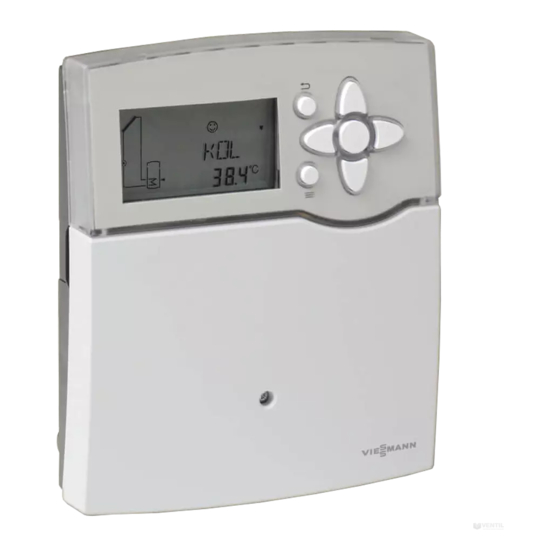
- Page 1 VIESMANN Installation and service instructions for contractors Vitosolic 100 Type SD1 Electronic temperature differential control unit for Vitocell 100-U, type CVUA For applicability, see the last page VITOSOLIC 100 Please keep safe. 5774 010 GB 2/2010...
- Page 2 Replace faulty components only with original Viessmann spare Regulations parts. Observe the following when working on this system ■ all legal instructions regarding the pre- vention of accidents, ■...
- Page 3 Installing non-authorised components and non-approved modifications or conversions can compromise safety and may invalidate our warranty. For replacements, use only orig- inal spare parts supplied or approved by Viessmann.
-
Page 4: Table Of Contents
Index Index Installation instructions Preparing for installation Installation information..................System example....................Installation sequence Mounting the solar control unit (when replacing)..........11 Overview of electrical connections............... 12 Solar circuit pump....................12 Pump/valve at output R2..................14 High limit safety cut-out..................15 Collector temperature sensor................ - Page 5 Index Index (cont.) Heat statement..................... 38 Speed control....................... 38 Parts list......................40 Specification....................... 41 Appendix......................42 Certificates Declaration of conformity..................43 Keyword index....................44...
-
Page 6: Preparing For Installation
■ The electronic temperature limit (up to ■ DHW cylinder Vitocell 100-U, type 90 °C) set in control unit eZ is excee- CVUA ■ Vitosolic 100, type SD1 ■ The temperature selected at high limit ■ Solar-Divicon (integrated into Vitocell safety cut-out qW (if installed) is... - Page 7 Preparing for installation System example (cont.) DHW heating without solar energy The top section of DHW cylinder qP is heated by boiler 1. The cylinder tem- perature controller with cylinder temper- ature sensor 3 of boiler control unit 2 regulates cylinder heating 4. Required settings on the solar control unit Delivered Description...
- Page 8 Preparing for installation System example (cont.) Hydraulic installation scheme ID: 4605119_1001_01...
- Page 9 Circulation pump R2 (transfer) (on site) Solar collectors Collector temperature sensor S1 Solar-Divicon (integrated into Vitocell 100-U, type CVUA) with Solar circuit pump R1 Vitosolic 100, type SD1 (integrated into Vitocell 100-U, type CVUA) Junction box (on site) ON/OFF switch (on site)
- Page 10 Preparing for installation System example (cont.) Electrical installation scheme 230 V/50 Hz HLSC KM BUS 2 ID: 4605119_1001_01 A If the control unit is used in conjunc- tion with a variable speed solar cir- cuit pump with PWM control...
-
Page 11: Installation Sequence
Installation sequence Mounting the solar control unit (when replacing) Before closing the solar control unit, make all electrical connections and apply strain relief to all cables/leads. -
Page 12: Overview Of Electrical Connections
Installation sequence Overview of electrical connections T 4 A 250 V P = 2 VA AC 250 V 0,8 A AC 250 V 4(2) A 230 V IP 20, l, T40 50 Hz N R2 R1 N L 9 10 11 12 13 14 15 16 17 18 19 20 21 A Wiring chamber of the solar control... - Page 13 Installation sequence Solar circuit pump (cont.) Suitable pumps Standard solar circuit pumps High efficiency Pumps with PWM pumps without input PWM input Without individual With individual Note speed control speed control Use only solar cir- (with integral auxili- cuit pumps, not ary capacitor) heating circuit pumps.
-
Page 14: Pump/Valve At Output R2
Installation sequence Solar circuit pump (cont.) Pump with PWM input Wiring chamber of the solar R1/PWM Solar circuit pump control unit Pump/valve at output R2 Installation Pump and valve must be type-tested and installed in accordance with the manu- facturer's instructions. Connection 3-core cable with a cross-section of Rated current: max. -
Page 15: High Limit Safety Cut-Out
Installation sequence Pump/valve at output R2 (cont.) A Wiring chamber of the solar control B Pump or valve unit High limit safety cut-out A high limit safety cut-out in the con- Note sumer is required when less than For the Vitocell 100-U, type CVUA, note 40 litres cylinder volume is available per that the max. -
Page 16: Collector Temperature Sensor
Installation sequence High limit safety cut-out (cont.) A Wiring chamber of the solar control unit B High limit safety cut-out C Solar circuit pump D Junction box (on site) Temperature setting Delivered condition: 120 °C High limit safety cut-out installa- Change to 95 °C tion instructions Collector temperature sensor... -
Page 17: Cylinder Temperature Sensor
Installation sequence Collector temperature sensor (cont.) Note Never route this lead immediately next to 230/400 V cables over long distances. Cylinder temperature sensor Installation With the threaded elbow. DHW cylinder installation instruc- tions Temperature sensor For additional functions see chapter "Function description". - Page 18 Installation sequence Temperature sensor (cont.) Installation Note Do not wrap insulating tape around the sensor. Seal in the sensor well. Connection Connect the sensor to S3 (terminals 5 Note and 6). Never route this cable immediately next Extension of the connecting cable: to 230/400 V cables.
-
Page 19: Power Supply
Installation sequence Power supply Regulations Carry out the power supply connection Protect the power cable to the control and all earthing measures (i.e. RCD cir- unit with an appropriate fuse/MCB. cuit) in accordance with IEC 364, the requirements of your local power supply utility and VDE [or local regulations]. -
Page 20: Commissioning
Commissioning Switching the power ON 1. Check whether all electrical connec- 4. After replacing the control unit: Check tions have been correctly made. which type of solar circuit pump is connected and set parameter 2. Check that the high limit safety cut- "RPM"... - Page 21 Commissioning Navigation through the menu (cont.) Calling up the menu The symbol line on the display shows which keys to use to make adjustments and call up informa- tion. Note After approx. 4 min, the display changes to show the collector temperature, if no further adjustments are made.
-
Page 22: Selecting The System Scheme
Commissioning Selecting the system scheme Press the following keys: for the required scheme. "ANL 1" and the respective 4. OK to confirm. scheme appear on the display. See system scheme from page 30. 2. OK "SET" flashes. Setting system parameters Press the following keys: 3. - Page 23 Commissioning Carrying out a relay test (cont.) for the required setting. Auto Control mode ON (100 %) "Æ" and "Â" and/or "Ã" is displayed and "¨" flashes. OFF OFF "Æ" is displayed and "¨" flashes. 5. OK to confirm. 6. After the relay test has been comple- ted, select "Auto".
-
Page 24: Service Scans
Service scans Calling up temperatures and operating conditions Subject to the system configuration and settings made, the following values can be called up with the keys: Display Description °C Collector temperature TSPU °C DHW temperature °C Temperature at sensor S3 if connected % Relative speed of the solar circuit pump Status of relay R2: OFF: Relay off... -
Page 25: Troubleshooting
Troubleshooting Fault messages Sensor faults: Possible displays: ■ Display background light flashes –88.8 Sensor short circuit ■ The sensor symbol in the system 888.8 Sensor lead break scheme flashes quickly ■ ¨ flashes Note Further information can be called up with keys Example - collector temperature sen- sor short circuit... -
Page 26: Changing The Fuse
Troubleshooting Checking sensors (cont.) Specification Sensor NTC 10 kΩ at 25 °C 20 kΩ at 25 °C IP rating IP 53 IP 53 Permissible ambient temperature ■ During operation −20 to + 90 °C −20 to + 200 °C ■ During storage and −20 to + 70 °C −20 to + 70 °C transport... -
Page 27: Function Description
Function description Parameter overview The following parameters can be set subject to the actual system configura- tion: Display Parameter Delivered Setting range System condition scheme System scheme 1–10 — DT E Start temperature differen- 8 °C 1.5 – 20 °C tial for solar circuit pump R1 DT E <... - Page 28 Function description Parameter overview (cont.) Display Parameter Delivered Setting range System condition scheme Collector limit temperature 130 °C 110 – 200 °C (see page 35) Collector cooling function OFF/ON (maximum collector temper- 110 °C 90 – 190 °C ature limit) (see page 36) 1 to 10 Minimum collector tempera-...
- Page 29 Function description Parameter overview (cont.) Display Parameter Delivered Setting range System condition scheme OWMZ Heat statement OFF/ON (see page 38) VMAX 5.0 l/min 0.1 – 20 l/min at 100 % pump speed MEDT 0 – 3 MED% 20 – 70 1 to 10 Speed control Depend-...
-
Page 30: System Scheme
Function description System scheme 10 system schemes can be achieved ■ Collector minimum temperature limit with the solar control unit. The selection (see page 36) is made via parameter "ANL" (see ■ Frost protection function (see page 22). All system schemes include page 37) the "ANL 1"... - Page 31 Function description System scheme (cont.) "ANL" = 1 — Standard scheme Dual mode DHW heating with suppression of reheating by the boiler in con- junction with control units with KM BUS Display Temperature differential control Determination of the temperature differential between col- lector temperature sensor S1 and cylinder temperature sensor S2.
- Page 32 Function description System scheme (cont.) "ANL" = 2 Selection cannot be applied. "ANL" = 3 Dual mode DHW heating and thermostat function Display Thermostat function Output R2 is used for this function. Relay R2 switches subject to the temperature at S3 (see the following table).
- Page 33 Function description System scheme (cont.) "ANL" = 4 Dual mode DHW heating and auxiliary function Display Additional function for DHW heating ■ Connection of the transfer pump at R2. ■ Signal for starting the transfer pump R2 via the KM BUS of the boiler control unit.
- Page 34 Function description System scheme (cont.) "ANL" = 6 Dual mode DHW heating and maximum cylinder temperature control Display ■ When set cylinder temperature "S SL" is exceeded (see page 31) the circulation pump R2 will start. ■ Excess heat is transferred, e.g. to the pre-heating stage. "ANL"...
-
Page 35: Collector Limit Temperature
Function description System scheme (cont.) "ANL" = 8 Dual mode DHW heating, auxiliary function and transfer with sensor S3 in DHW cylinder 2 (existing) Display The transfer pump R2 circulates the heating water to pre- vent stratification (see page 34) and implements the aux- iliary function (see page 33). -
Page 36: Collector Cooling Function
Function description Collector limit temperature (cont.) Setting parameters Delivered condition Setting range 130 °C 110 – 200 °C Note If the setting is 200 °C then the function is disabled. Collector cooling function The solar circuit pump is switched off 1. -
Page 37: Frost Protection Function
Function description Frost protection function Enable this function only when using 1. Set "OKF" to "On" (see page 22). water as heat transfer medium. If the collector temperature falls below 2. Set the value for "KFR". the "KFR" value, the solar circuit pump is switched on to avoid collector dam- age. -
Page 38: Heat Statement
Solar-Divicon at 100 % speed and set that value as "VMAX". MEDT setting Heat transfer medium Water Propylene glycol Ethylene glycol Viessmann heat transfer medium Setting parameters Delivered condition Setting range VMAX 5.0 l/min 0.1 – 20 l/min MEDT 0 –... - Page 39 Function description Speed control (cont.) Example DT E = 5 K DT S = 10 K ANS = 2 K 10 12 14 Temperature differential in K...
-
Page 40: Parts List
(as per this parts list). Standard parts are available from your local supplier. Parts 300 Vitosolic 100, type SD1 311 Collector temperature sensor 312 Cylinder temperature sensor 313 Solar circuit pump connecting cable... -
Page 41: Specification
Specification Specification Rated voltage 230 V∼ Rated frequency 50 Hz Rated current 4 A∼ Power consumption (0.7 W in standby mode) Safety category IP rating IP 20 D to EN 60529, ensure through design/instal- lation Mode of operation Type 1 B to EN 60730-1 Permiss. -
Page 42: Appendix
Appendix Appendix Replace the PCB in the stated boiler control units in conjunction with the fol- lowing functions: ■ Suppression of reheating by the boiler ■ Auxiliary function for DHW heating, achieved by the solar control unit Control unit Vitotronic 200, type KW1, Part no. -
Page 43: Certificates
Certificates Declaration of conformity We, Viessmann Werke GmbH & Co KG, D-35107 Allendorf, confirm as sole respon- sible body that the product Vitosolic 100 complies with the following standards: EN 55 014-1 EN 60 730 This product is designated _ in accordance with the following Directives:... -
Page 44: Keyword Index
Keyword index Keyword index Anti-scalding protection....6, 33 Navigation through the menu.....20 Applicability........48 Automatic mode......20, 22 Auxiliary function for DHW heating..33 Operating steps........20 Overview of electrical connections..12 Changing settings......22 Changing the fuse......26 Parts list..........40 Checking sensors......25 Power supply........19 Collector cooling function....36 Pump at R2........14 Collector limit temperature....35 Pumps..........12... - Page 48 Applicability Applicable for the Vitosolic 100, type SD1 solar control unit Part no. 7418 201 and 7439 960 Viessmann Werke GmbH&Co KG Viessmann Limited D-35107 Allendorf Hortonwood 30, Telford Telephone: +49 6452 70-0 Shropshire, TF1 7YP, GB Fax: +49 6452 70-2780 Telephone: +44 1952 675000 www.viessmann.com...
Need help?
Do you have a question about the Vitosolic 100 and is the answer not in the manual?
Questions and answers