Viessmann SM1 Installation And Service Instructions Manual
Solar control module
Hide thumbs
Also See for SM1:
- Installation and service instructions manual (52 pages) ,
- Installation and service instructions manual (28 pages)
Table of Contents
Advertisement
Quick Links
Installation and Service
Instructions
for use by heating contractor
Solar Control Module
for solar connections to the Vitotronic control
SM1
SOLAR CONTROL MODULE
Certified as a component
part for Viessmann boilers
5774 469 v1.0 09/2013
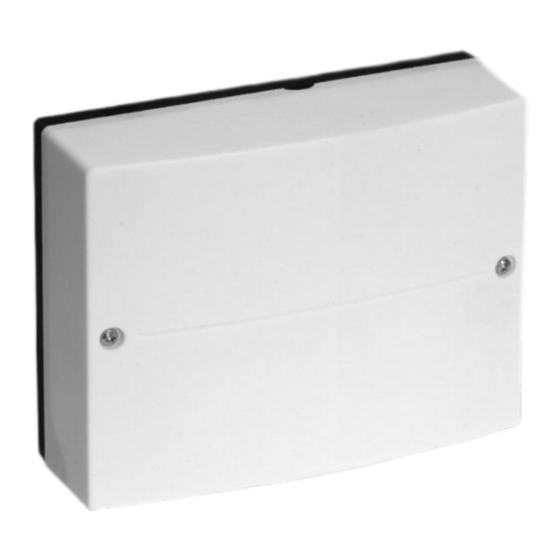
Product may not be exactly as shown
IMPORTANT
Read and save these instructions
for future reference
.
Please file in Service Binder
Advertisement
Table of Contents

Related Manuals for Viessmann SM1


Summary of Contents for Viessmann SM1
- Page 1 Vitotronic control SOLAR CONTROL MODULE Product may not be exactly as shown IMPORTANT Read and save these instructions Certified as a component for future reference part for Viessmann boilers 5774 469 v1.0 09/2013 Please file in Service Binder...
-
Page 2: Safety, Installation And Warranty Requirements
Safety Solar Control Module SM1, Installation and Service Safety, Installation and Warranty Requirements Please ensure that these instructions are read and understood before commencing installation. Failure to comply with the instructions listed below and details printed in this manual can cause product/property damage, severe personal injury, and/or loss of life. -
Page 3: Table Of Contents
Table of Contents Solar Control Module SM1, Installation and Service Page Safety, Installation and Warranty Requirements....2 Safety Product documentation...........2 Licensed professional heating contractor....2 Advice to owner............2 Warranty...............2 Important Regulatory and Installation Requirements..4 Important Precautions Approvals.............4 Codes..............4 Working on the equipment........4 Power supply............4... -
Page 4: Important Regulatory And Installation Requirements
Important Precautions Solar Control Module SM1, Installation and Service Important Regulatory and Installation Requirements Please carefully read this manual prior to attempting Approvals installation. Any warranty is null and void if these Viessmann boilers, burners and controls are approved for instructions are not followed. -
Page 5: About These Installation Instructions
General Information Solar Control Module SM1, Installation and Service About these Installation Instructions Take note of all symbols and notations intended to draw attention to potential hazards or important product information. Indicates an imminently hazardous situation which, WARNING if not avoided, could result in death, serious injury or substantial product/property damage. -
Page 6: Mounting On The Wall
Installation Solar Control Module SM1, Installation and Service Mounting on the Wall Extension kit for installation on a wall 1. Loosen the retaining screws from the extension kit enclosure (do not remove). 2. Remove cover and set aside. 3. Mount the extension module enclosure to the wall using the supplied hardware. -
Page 7: Overview Of Electrical Connections
Connections Solar Control Module SM1, Installation and Service Overview of Electrical Connections Legend Solar control module DHW tank temperature sensor CAUTION & Collector temperature sensor Electronic modules can be damaged by electrostatic Temperature sensor (accessory) charges. aÖ Temperature sensor (accessory) -
Page 8: System Example 1
Connections Solar Control Module SM1, Installation and Service System Example 1 DHW heating with dual mode DHW tank Suppression of DHW tank reheating by the boiler Function description Reheating suppression takes place in two stages. DHW heating with solar energy... - Page 9 Connections Solar Control Module SM1, Installation and Service System Example 1 (continued) Hydraulic installation scheme Equipment required Legend 1 Wall mounted oil/gas boiler with 2 Boiler and heating circuit control unit qT Circulation pump sS (transfer of heat, on site)
- Page 10 Connections Solar Control Module SM1, Installation and Service System Example 1 (continued) Electrical installation scheme Solar control module, type SM1...
-
Page 11: System Example 2
Connections Solar Control Module SM1, Installation and Service System Example 2 Additional function for DHW heating DHW heating with two mono mode DHW tanks The requirements for the additional function are achieved Function description through circulation pump qT. DHW heating with solar energy... - Page 12 Connections Solar Control Module SM1, Installation and Service System Example 2 (continued) Hydraulic installation scheme Equipment required Legend 1 Wall mounted oil/gas boiler with qZ Temperature sensor / (accessory) 2 Boiler and heating circuit control unit qU Temperature sensor aÖ (accessory)
- Page 13 Connections Solar Control Module SM1, Installation and Service System Example 2 (continued) Electrical installation scheme Solar control module, type SM1 A KM BUS to boiler control unit...
-
Page 14: System Example 3
Connections Solar Control Module SM1, Installation and Service System Example 3 DHW heating with mono mode DHW tank and central Suppression of heating water buffer DHW tank reheating heating backup with multi mode heating water buffer by the boiler with DHW heating DHW tank with differential temperature control Reheating suppression takes place in two stages. - Page 15 Connections Solar Control Module SM1, Installation and Service System Example 3 (continued) Central heating with solar energy Central heating without solar energy If the temperature differential between sensor rW and If the temperature differential between sensor rW sensor rT is greater than the temperature differential...
- Page 16 Connections Solar Control Module SM1, Installation and Service System Example 3 (continued) Hydraulic installation scheme Equipment required Legend 1 Wall mounted oil/gas boiler with eZ Solar control module, type SM1 2 Boiler and heating circuit control unit eU Junction box (on site)
- Page 17 Connections Solar Control Module SM1, Installation and Service System Example 3 (continued) Electrical installation scheme Solar control module, type SM1 A KM BUS to boiler control unit...
-
Page 18: Power Supply
Connections Solar Control Module SM1, Installation and Service Power Supply Connect accessories with a total wattage above 400 W directly to the mains power supply. WARNING Incorrectly executed electrical installations can result in injuries from electrical current and in equipment damage. -
Page 19: Connecting The Km Bus To The Extension Modules
Connections Solar Control Module SM1, Installation and Service Connecting the KM BUS to the Extension Modules Legend A Boiler control unit B Extension kit for heating circuit with mixing valve M2 C Extension kit for heating circuit with mixing valve M3... -
Page 20: Connection And Wiring Diagram
Connections Solar Control Module SM1, Installation and Service Connection and Wiring Diagram Legend Main PCB Temperature sensor (if installed) aÖ PWM Speed control, solar circuit pump (if circulation Temperature sensor (if installed) pump with PWM control installed) Transfer pump or 3-way diverter valve... -
Page 21: Function Description
Additional Information Solar Control Module SM1, Installation and Service Function Description Note: Set or alter the functions described below in coding Thermostat function levels 1 and 2 (solar group) at the boiler control unit. The thermostat function can be used independently of the solar operation. - Page 22 Additional Information Solar Control Module SM1, Installation and Service Function Description (continued) Suppression of DHW tank reheating by the boiler External heat exchanger Reheating suppression takes place in two stages. Reheating of the DHW tank by the boiler is suppressed as soon as the DHW tank is heated by the collectors.
-
Page 23: Specifications
Additional Information Solar Control Module SM1, Installation and Service Specifications Rated voltage 120 V~ Rated frequency 60 Hz Rated current Power consumption 1.5 W Protection class IP rating IP 20 D to EN 60 529, ensure through design/ installation Permissible ambient temperature H During operation 32 to 104°...
Need help?
Do you have a question about the SM1 and is the answer not in the manual?
Questions and answers