Advertisement
Proportional Digital Control Signal Input and
Applications
©
1993 Johnson Controls, Inc.
Part No. 34-636-70
Rev—
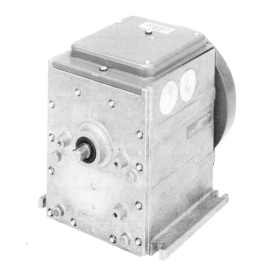
M100C Series of Motor Actuators with
R81C Interface Board
The M100C Series Motor Actuator is used in damper and valve
applications where proportional control from a digital controller is
required.
The M100C has the capability of communicating with Metasys ®
AHU/UNT or DSC1000 controllers depending on the position of the 8-pin
DIP switch. Other functions that are user programmable include master or
slave configuration, direct or reverse acting mode, the address to which the
actuator will respond and the linear or S-curve response characteristic.
Installation Sheets Manual 121
Motor Actuators Section M
Figure 1: M100
Technical Bulletin M100C
Issue Date 0493
1
Advertisement
Table of Contents

Related Manuals for Johnson Controls M150


Summarization of Contents
Technical Specifications
Torque Ratings
Lists torque specifications for different M100 models.
Power Source and Accessories
Details available input voltage options and factory-mounted accessories.
Control Input and Travel
Describes digital control input and the actuator's travel and timing characteristics.
Physical and Operational Details
Direction of Rotation
Explains how to interpret the direction of rotation for the actuator's load end.
Dimensions
Provides physical dimensions of the M100 Series Motor Actuator.
Installation Procedures
Tools, Safety, and Mounting
Lists required tools, safety precautions, code requirements, and mounting guidelines.
R81 Circuit Board Installation
Removing and Installing Boards
Steps to safely remove existing and install new circuit boards, including terminal and vertical boards.
Wiring Diagrams
Single Unit and Parallel Master Wiring
Diagrams for single M100 units and parallel systems with master actuators.
Calibration and Configuration
DIP Switch Settings
Using the 8-position DIP switch to configure operating parameters like master/slave and response curves.
Operation Modes and Characteristics
Master/Slave and Flow Curves
Setting master/slave configurations and understanding linear/S-curve flow characteristics.
Actuator Control Settings
Action, Bus, and Address Configuration
Setting direct/reverse action, communication bus, and unique addresses via DIP switches.
Controller Specific Addressing
C500 Controller Address Selection
Details on selecting addresses for C500 controllers, referring to technical bulletins and switch settings.
Sequence Operations and AHU Addressing
Sequence Modes and AHU Addressing
Describes sequence operation modes and AHU controller address assignment via software.
Advanced Settings and Adjustments
AHU Address Switches and Travel Adjustment
AHU address switch settings and adjusting the actuator's rotation range.
Travel Adjustment Procedure
Full Range Rotation Example
Illustrates how controller commands translate to actuator rotation for full range operation.
Troubleshooting and Maintenance
Operational Check and Replacement
Procedures for verifying operation, maintenance, and contacting support for parts or repairs.
Need help?
Do you have a question about the M150 and is the answer not in the manual?
Questions and answers