
Related Manuals for Ravas SafeLoad


Summary of Contents for Ravas SafeLoad
- Page 1 INSTALLATION MANUAL RAVAS-SafeLoad Rev.20211209 Printing/typographical errors and model changes reserved INSTALLATION MANUAL – RAVAS-SafeLoad...
- Page 2 This manual has been compiled with all due care, but the manufacturer cannot be held responsible for any errors or the consequences thereof. All rights are reserved and no part of this manual may be reproduced in any way. INSTALLATION MANUAL – RAVAS-SafeLoad...
-
Page 3: Table Of Contents
Parameter setting mode ................... 28 7.2. Weight parameters ................... 28 7.3. Moment parameters ..................30 7.4. LED bar, logging and backlight parameters ............31 7.5 Checking the parameters audit trail number for registration (recommended) .. 33 INSTALLATION MANUAL – RAVAS-SafeLoad... - Page 4 Debug mode (for troubleshooting) ..............36 9. User MENU ......................37 9.1 Setting the date and time .................. 37 9.2 Setting the backlight ..................37 9.3 Reading the Bluetooth address ................ 38 9.4 Passcode ......................38 INSTALLATION MANUAL – RAVAS-SafeLoad...
-
Page 5: Introduction
This manual should be kept in a dry and safe place. In case of damage or loss the user may request a new copy of the manual from RAVAS. This manual is based on firmware version 0.31 and higher. -
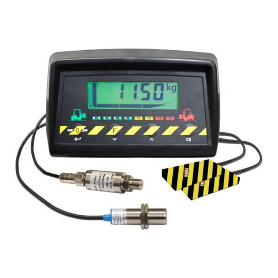
Page 6: Overview Of The Parts
12, 24, 48 and 80 V. In cases where the battery voltages are higher then 12 VDC, the system demands a DC-DC voltage converter with an output of 12 Vdc. Only by RAVAS approved convertors may be used. If other convertors are used the warranty of the indicator is no longer valid. -
Page 7: Before The Installation
The RAVAS-SafeLoad will operate optimally at an oil pressure up to 350 bar. 4.3. Battery voltage of the forklift truck The most common voltages for forklift trucks are 12, 24, 48 and 80 VDC. The RAVAS-SafeLoad operates on 12 Vdc and can handle voltage differences between 9VDC and 18VDC. In cases where the battery voltage is greater than 12 Vdc, the system requires a DC-DC power converter with an output voltage of 12 Vdc. -
Page 8: The Condition Of Mechanical Components Of The Forklift Truck
The condition of mechanical components of the forklift truck After installation of the RAVAS-SafeLoad system on the forklift truck, the truck is part of the system. In particular the mechanical parts of the forklift truck, such as the mast, mast roles and bearings, will influence the accuracy of the weightings. -
Page 9: Installation
Place the sensor close to the cylinder. There is often more room there and it is easier to reach. Choose, if possible, a place to mount the sensor where there are the least steering and safety valves between the sensor and the cylinder. INSTALLATION MANUAL – RAVAS-SafeLoad... - Page 10 Type A: 1 central cylinder Mount the T-piece into the delivery line of the truck near the cylinder for the diversion of the pressure to the SafeLoad. INSTALLATION MANUAL – RAVAS-SafeLoad...
- Page 11 Type B: 2 cylinders on both sides Mount the T-piece into the delivery line of the truck near the cylinder for the diversion of the pressure to the SafeLoad INSTALLATION MANUAL – RAVAS-SafeLoad...
-
Page 12: Hydraulics: Mounting The Oil Pressure Sensor
5.2. Hydraulics: mounting the oil pressure sensor The connector on the sensor is G 1/4 "BSP male INSTALLATION MANUAL – RAVAS-SafeLoad... -
Page 13: Mechanics: Installing The Moment Force Sensors
2 protection caps, to be installed over the force sensors 1 junction box, to be installed at a suitable place in the truck. For mounting the force sensors you may drill holes or use stud welds. INSTALLATION MANUAL – RAVAS-SafeLoad... -
Page 14: Mechanics: Installing The Height Switch
Height switch is activated in lowest Height switch is deactivated as soon as the second or position of the mast third mast stage is reached For mounting the height switch brackets we recommend using Loctite adhesive materials: Adhesive 326 Activator 7649 INSTALLATION MANUAL – RAVAS-SafeLoad... -
Page 15: Mechanics: Installing The Indicator
5.5. Mechanics: installing the indicator Position of the indicator The indicator should be easy to reach and read out! Installing the indicator INSTALLATION MANUAL – RAVAS-SafeLoad... -
Page 16: Electronics: Mounting The Cables
The system is supplied with a protective cover for the cable. This can be used where: the cable is near parts of the lift truck that become hot; the cable is mounted near moving parts. INSTALLATION MANUAL – RAVAS-SafeLoad... -
Page 17: Electronics: Wiring Drawing Indicator
5.7. Electronics: wiring drawing indicator INSTALLATION MANUAL – RAVAS-SafeLoad... -
Page 18: Electronics: Relay Option Connections
5.8. Electronics: relay option connections INSTALLATION MANUAL – RAVAS-SafeLoad... -
Page 19: Electronics Connecting The Power Supply Cable
12 V wire Arrange power supply from the truck The RAVAS-SafeLoad indicator is standardly suited for 12 VDC power supplied trucks, so it can be connected to a 12VDC power supply only. (variance 9 to 18VDC) For trucks which have a ‘dirty’ power supply a filter is recommended. The RAVAS-SafeLoad comes standard with an internal 12V regulator board. -
Page 20: Remove Any Air From The Hydraulic System
5.10. Remove any air from the hydraulic system Bring the forks to maximum height twice to remove any remaining air from the hydraulic system. INSTALLATION MANUAL – RAVAS-SafeLoad... -
Page 21: Calibration
Calibration 6.1. Preparing for calibration 90° ", Recommended calibration weight: M1 = +/- 2/3 of the truck’s lifting capacity 2.2t truck => M1 = 1500 EXAMPLE #1: < min -10°C max 40°C 15°F 105°F INSTALLATION MANUAL – RAVAS-SafeLoad... -
Page 22: Bring The Forklift Truck To Operating Temperature
Weight Units Stable sign. Approximate LCP indication Possible unsafe situation if lid Zero (1s.) Special function Setting Time Clear Enter (for future use) and Date(10s.) arrow down Arrow up (press 10s.) Calibration and debug mode INSTALLATION MANUAL – RAVAS-SafeLoad... - Page 23 INSTALLATION MANUAL – RAVAS-SafeLoad...
-
Page 24: Calibration Procedure
6.4.1. Entering the calibration mode Power up the truck to start the RAVAS-SafeLoad indicator. o The buzzer (if activated) will beep shortly and the display will show in the following order; all segments on, the software version and the present weight. - Page 25 1 picture 2 picture 3 picture 4 picture 5 Example load diagram forklift truck INSTALLATION MANUAL – RAVAS-SafeLoad...
- Page 26 1 of the indicator. If there is no switch available or used this step may be performed in the same position as the lower span-adjustment. o The display will shortly show [Adj]. o The display will show [ AP9] and countdown to [ AP0] INSTALLATION MANUAL – RAVAS-SafeLoad...
- Page 27 6.4.4. Checking the calibrations audit trail number for registration (recommended) Power up the truck to start the RAVAS-SafeLoad indicator. The buzzer (if activated) will beep shortly and the display will show in the following order; all segments on/green backlight on/all LEDs of the LED-bar on, the software version with red backlight and the present weight.
-
Page 28: Parameter Settings
Parameter settings 7.1. Parameter setting mode Power up the truck to start the RAVAS-SafeLoad indicator. The buzzer (if activated) will beep shortly and the display will show in the following order; all segments on, the software version and the present weight. - Page 29 0;20; 40; 80; 160; 320 seconds backlight brightness 100/150/175/200 Software versie Fixed value (installed) Audit trail number Changes whenever a parameter is being parameters changed Audit trail number Changes whenever a new calibration is calibration performed INSTALLATION MANUAL – RAVAS-SafeLoad...
- Page 30 [L1=500], select 1620 for position L2=600 [H1=500], select 1080 for position H2=600 and select 1470 for position L3=700 (in this and select 980 for position H3=700 (in this example) example) INSTALLATION MANUAL – RAVAS-SafeLoad...
- Page 31 Note 4: P_009 and P_010 have 2 settings for the zero range of the auto track zero and the manual zero. Default the value for the auto zero track range will be +8% and -2% and for the manual zero it will be 20%. INSTALLATION MANUAL – RAVAS-SafeLoad...
-
Page 32: Moment Parameters
00-00 Display will show [WAIT] until all errors are messages(with timestamp) completely loaded. Backup initial parameter 00000 settings + calibration Measurement on/off On; OFF Key test function (Buzzer and nr) Software version (last 0.31 available version) INSTALLATION MANUAL – RAVAS-SafeLoad... -
Page 33: Led Bar, Logging And Backlight Parameters
0%-100% of max capacity Reset dynamic event ±2% ±0%-100% of max capacity On/Off Activate error messages for new version hardware (implementation Juli 2017) On/Off For internal use only(changing this setting could cause errors in normal weighing mode) INSTALLATION MANUAL – RAVAS-SafeLoad... - Page 34 The display will show [Wght]. Press the CE-key again to leave the settings menu and return to the weigh mode. The settings may be altered according own experiences and wishes. The default settings are given in the table. INSTALLATION MANUAL – RAVAS-SafeLoad...
-
Page 35: Checking The Parameters Audit Trail Number For Registration (Recommended)
Checking the parameters audit trail number for registration (recommended) Power up the truck to start the RAVAS-SafeLoad indicator. The buzzer (if activated) will beep shortly and the display will show in the following order; all segments on/green backlight on/all LEDs of the LED-bar on, the software version with red backlight and the present weight. -
Page 36: Error Messages
OLOAD* Overload on maximum moment Remove the weight from the forks or replace the weight more to the vertical part of the forks OLOAD* Overload on maximum weight and Remove the weight moment from the forks INSTALLATION MANUAL – RAVAS-SafeLoad... - Page 37 Lowering the mast a little should be sufficient to cancel the error message. *2: If the height sensor cable is broken, the RAVAS-SafeLoad will always presume that the forks are in the second mast stage. In the lowest mast position you are most likely to see the underload error [-----] with no load on the forks even if the forks are raised from the floor.
-
Page 38: Checking The Logged Errors
Checking the logged errors For checking the last 50 errors of the RAVAS-SafeLoad enter the parameter mode as described on page 25 (7.1 Parameter setting mode). After entering the parameter number press the -key. o The display will gather all the errors from the memory and eventually show [00-xx]. -
Page 39: User Menu
The display will show [LIgHt]. press the -key for 3 seconds to save the new backlight settings. o The display will show [Set__]. o The user menu is closed off and the system returns to the normal function mode INSTALLATION MANUAL – RAVAS-SafeLoad... -
Page 40: Reading The Bluetooth Address
[<< 2<< _2E<< 2E7<<_2E71<<2E715<<E7154<< 2<<]. Press the CE-key twice for returning back in the normal function mode. Passcode For entering a menu a passcode may be required. The standard passcode for the SafeLoad is [5220]. INSTALLATION MANUAL – RAVAS-SafeLoad...
Need help?
Do you have a question about the SafeLoad and is the answer not in the manual?
Questions and answers