Table of Contents
Advertisement
Quick Links
INSTALLATION, OPERATING AND
SERVICE INSTRUCTIONS FOR
For service or repairs to boiler, call your heating contractor. When seeking information on boiler,
provide Boiler MOdel Number and Serial Number as shown on Rating Label.
Boiler Model Number
LE
Heating Contractor
Address
103626-04 - 3/18
®
LE
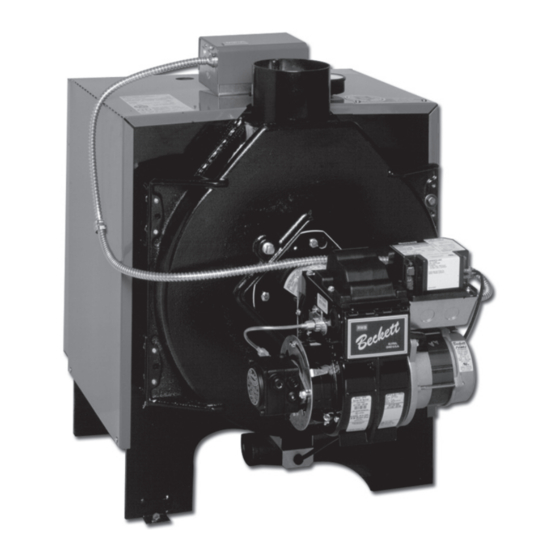
OIL - FIRED BOILER
Boiler Serial Number
SERIES
Installation Date
Phone Number
Price - $5.00
Advertisement
Table of Contents

Related Manuals for U.S. Boiler Company LE Series


Summary of Contents for U.S. Boiler Company LE Series
- Page 1 INSTALLATION, OPERATING AND SERVICE INSTRUCTIONS FOR ® SERIES OIL - FIRED BOILER For service or repairs to boiler, call your heating contractor. When seeking information on boiler, provide Boiler MOdel Number and Serial Number as shown on Rating Label. Boiler Model Number Boiler Serial Number Installation Date Heating Contractor...
- Page 2 IMPORTANT INFORMATION - READ CAREFULLY All boilers must be installed in accordance with National, State and Local Plumbing, Heating and Electrical Codes and the regulations of the serving utilities. These Codes and Regulations may differ from this instruction manual. Authorities having jurisdiction should be consulted before installations are made.
- Page 3 DANGER DO NOT store or use gasoline or other flammable vapors or liquids in the vicinity of this or any other appliance. WARNING Improper installation, adjustment, alteration, service or maintenance can cause property damage, personal injury or loss of life. Failure to follow all instructions in the proper order can cause personal injury or death.
-
Page 4: Table Of Contents
WARNING This boiler contains very hot water under 12 - 15 PSI pressure. DO NOT unscrew any pipe fittings nor attempt to disconnect any components of this boiler without positively assuring the water is cool and has no pressure. Always wear protective clothing and equipment when installing, starting up or servicing this boiler to prevent scald injuries. - Page 5 103626-04 - 3/18...
- Page 6 103626-04 - 3/18...
-
Page 7: General Information
I. GENERAL INFORMATION (continued) TABLE 1: RATING DATA Burner Capacity AHRI NET Heating Ratings - Boiler Model Capacity - AFUE % LE1L 0.60 86.7 Notes: 1. MBH refers to thousands of BTU per hour. 2. Based on Standard Test prescribed by the United States Department of Energy at combustion condition of 13.5% 3. -
Page 8: Pre-Installation
II. PRE-INSTALLATION 2. Boiler is suitable for installation on combustible INSPECT SHIPMENT carefully for any signs of damage. floor. DO NOT install boiler on carpeting. 1. All equipment is carefully manufactured, inspected 3. For basement installation, provide a solid elevated and packed. - Page 9 II. PRE-INSTALLATION (continued) REMOVE CRATE 3. Determine type of space. Divide Volume by total input of all appliances in space. If the result is greater than 1. Remove all fasteners at crate skid. or equal to 50 ft /1000 BTU per hour, then it is 2.
-
Page 10: Packaged Boiler Assembly - Trim And Controls
III. PACKAGED BOILER ASSEMBLY - TRIM AND CONTROLS 7. Replace door assembly. Hinge brackets attached to CHANGE HINGE POSITION door must rest on top of hinge brackets attached to 1. Look at the area where boiler will be installed. If Tubesheet. - Page 11 III. PACKAGED BOILER ASSEMBLY - TRIM AND CONTROLS (continued) 2. Riello 40F Burner: INSTALL BOILER CONTROL, refer to Figure 5A or Step a. Locate the L7248L Boiler Control/ Transformer - Relay Control Center/Harness 1. Beckett AFG Burner: Assembly in the carton secured to shipping skid. Step a.
- Page 12 III. PACKAGED BOILER ASSEMBLY - TRIM AND CONTROLS (continued) Figure 5B: Relief Valve and Boiler Control Assembly Details - Riello 40F Burner Figure 6: Limit Sensor Insertion 103626-04 - 3/18...
-
Page 13: Water Piping And Trim
Oxygen contamination of boiler water will cause corrosion of iron and steel boiler components, and can lead to boiler failure. U.S. Boiler Company’s Warranty does not cover problems caused by oxygen contamination of boiler water or scale (lime) build-up caused by frequent addition of water. - Page 14 103626-04 - 3/18...
- Page 15 103626-04 - 3/18...
- Page 16 IV. WATER PIPING AND TRIM (continued) gravity circulation of boiler water during the INSTALL DRAIN VALVE in return piping. See operation of the cooling system. Figures 8A and 8B. d. If boiler is used with an Indirect-Fired Domestic . OIL, GREASE, AND OTHER FOREIGN Water Heater, install the Indirect-Fired Domestic MATERIALS which accumulate in new hot water and a Water Heater as a separate heating zone.
-
Page 17: Venting
The combina- in your area. tion of a large uninsulated chimney, reduced 2. The LE Series is designed to be vented into a firing rate, reduced firing time, lower stack fireclay tile-lined masonry chimney or chimney... - Page 18 V. VENTING (continued) Figure 9: Recommended Smoke Pipe Arrangement and Chimney Requirements Figure 10: Draft Regulator Locations 103626-04 - 3/18...
-
Page 19: Electrical
VI. ELECTRICAL DANGER Positively assure all electrical connections are unpowered before attempting installation or service of electrical components or connections of the boiler or building. Lock out all electrical boxes with padlock once power is turned off. WARNING Failure to properly wire electrical connections to the boiler may result in serious physical harm. Electrical power may be from more than one source. - Page 20 103626-04 - 3/18...
- Page 21 103626-04 - 3/18...
- Page 22 VI. ELECTRICAL (continued) NOTE: APPLY THIS BURNER SCHEMATIC TO APPROPRIATE STEAM OR WATER BOILER CONTROL SCHEMATIC, REFER TO FIGURES 11A AND 11B NOTE: APPLY THIS BURNER SCHEMATIC TO APPROPRIATE STEAM OR WATER BOILER CONTROL SCHEMATIC, REFER TO FIGURES 11A AND 11B Figure 12: Schematic Wiring Diagrams For All Burner Options w/Various Oil Primary Controls 103626-04 - 3/18...
-
Page 23: Oil Piping
VII. OIL PIPING SINGLE-PIPE OIL LINES GENERAL 1. Standard burners are provided with single-stage 1. Use flexible oil line(s) so that burner can be re- 3450 rpm fuel units with the bypass plug removed moved without disconnecting the oil supply. for single-pipe installations. - Page 24 VII. OIL PIPING (continued) TABLE 3: SINGLE-STAGE UNITS (3450 RPM) - TABLE 4: TWO-STAGE UNITS (3450 RPM) - TWO PIPE SYSTEMS TWO PIPE SYSTEMS Maximum Length of Tubing Maximum Length of Tubing "H" + "R" (See Figure) "H" + "R" (See Figure) Lift "H"...
-
Page 25: System Start-Up
VIII. SYSTEM START-UP WARNING All boilers equipped with burner swing door have a potential hazard which can cause severe property damage, personal injury or loss of life if ignored. Before opening swing door, turn off service switch to boiler to prevent accidental firing of burner outside the combustion chamber. - Page 26 VIII. SYSTEM START-UP (continued) c. Inspect Beckett head setting on left side of 2. PRESS RED RESET BUTTON on burner primary burner housing by insuring that the witness control, hold for one second and release to reset the mark on the housing and the zero line on the control.
- Page 27 VIII. SYSTEM START-UP (continued) Figure 15: "L1" Fixed Head Electrode Positioning and Gun Setting (Beckett AFG) d Nozzle Replacement, refer to Figure 17. • Remove the AIR TUBE COVER i. Remove the NOZZLE ADAPTER (2) from PLATE (5) by loosening the retaining the DRAWER ASSEMBLY by loosening the SCREW (4) .
- Page 28 VIII. SYSTEM START-UP (continued) i. Pump Connections and Port Identification, refer to Figure 20. This burner is shipped with the oil pump set to operate on a single line system. To operate on a two-line system the bypass plug must be installed.
- Page 29 VIII. SYSTEM START-UP (continued) burner for a short period of time. Shut the burner START OIL BURNER. off. The pressure should drop and hold. 1. Open vent fitting on fuel pump. d. Turn "OFF" the burner. Remove the pressure 2. PRESS RED RESET BUTTON on primary control, gauge and install port/bleeder plug and/or hold for one (1) second and release to reset primary reconnect the nozzle port line and tighten.
- Page 30 VIII. SYSTEM START-UP (continued) 4. FLAME FAILURE TEST CONTROLS. The LE boiler controls operate the burner 1. Check thermostat operation. Raise and lower automatically. If for unknown reasons the burner thermostat setting as required to start and stop ceases to fire and the reset button on the primary burner.
- Page 31 VIII. SYSTEM START-UP (continued) • At burner start up, click the reset button 3. CHECK OIL PRIMARY CONTROL while the igniter is till on. This will CAUTION transition the control to a dedicated Pump Prime mode, during which the Due to the potential hazard of line voltage, only a motor, igniter, and valve are powered for trained, experienced service technician should four (4) minutes.
- Page 32 VIII. SYSTEM START-UP (continued) • After third Recycle Mode trial, safety c. Allow the temperature to drop below control setting. The burner must restart. switch locks out within safety switch timing indicated on label and control d. Boiler installation is not considered complete enters Restricted Mode.
-
Page 33: Operating
IX. OPERATING WATER BOILERS SEQUENCE OF OPERATION Water Boilers Without Tankless Heaters (Cold Start), Sequence Of Operation: a. The LE Boiler is equipped with an Intelligent Oil Boiler Control (cold start boiler control). The boiler control replaces the traditional electronic aquastat and circulator relays and adds energy saving thermal purge features. - Page 34 IX. OPERATING (continued) “I” Press and release the key on the Boiler Control Cold Start Boiler Control to change from one parameter to the next. Each Adjustment Mode Options setting will alternately flash between the relevant 140-240°F Adjust High Limit Setting display code and its corresponding value.
- Page 35 IX. OPERATING (continued) TABLE 8: CIRCULATOR PRE-PURGE TIME EXAMPLE, TABLE 9: DOMESTIC HOT WATER DEMAND, PARAMETER PP_= 2 MINUTES (PARAMETER ZC_= DH) ZC and ZR Call for Heat Circulator Status Call for Terminal Boiler Boiler Status, Priority System Heat Temp. Function (B1 Output) Circulator...
- Page 36 IX. OPERATING (continued) TABLE 10: ZONE REQUEST, PARAMETER ZC_= ZR TABLE 11: EXTERNAL LOW LIMIT, PARAMETER ZC_= ELL Call for Heat Circulator Status Call for Heat Circulator Status Input Input Output Output Input Input Output Output ii. When ZC_ is set equal to Zone Request (ZR) iii.
-
Page 37: Maintenance And Service Instructions
X. MAINTENANCE AND SERVICE INSTRUCTIONS After boiler and system have been cleaned and WATER BOILERS: refilled as previously described, test the pH of the 1. Filling of boiler and system. water in the system. This can easily be done by GENERAL —... - Page 38 X. MAINTENANCE AND SERVICE INSTRUCTIONS (continued) 3. Always keep the manual fuel supply valve shut off ATTENTION TO BOILER WHILE NOT IN if the burner is shut down for an extended period of OPERATION time. NOTICE 4. To recondition the heating system in the fall season after a prolonged shut down, follow the instructions If boiler is not used during winter time, it must be outlined in Section VIII, System Start-Up, Para-...
-
Page 39: Boiler Cleaning
XI. BOILER CLEANING WARNING All boiler cleaning must be completed with burner service switch turned off. Boilers equipped with burner swing door have a potential hazard which can cause severe property damage, personal injury or loss of life if ignored. Before opening swing door, turn off service switch to boiler to prevent accidental firing of burner outside the combustion chamber. - Page 40 XI. BOILER CLEANING (continued) Figure 26: Cleaning of LE Boiler Firetubes / Combustion Chamber WARNING The boiler must be connected to an approved chimney in good condition. Serious property damage could result if the boiler is connected to a dirty or inadequate chimney. The interior of the chimney flue must be inspected and cleaned before the start of the heating season and should be inspected periodically throughout the heating season for any obstructions.
- Page 41 Important Product Safety Information Refractory Ceramic Fiber Product Warning: The Repair Parts list designates parts that contain refractory ceramic fibers (RCF). RCF has been classified as a possible human carcinogen. When exposed to temperatures above 1805°F, such as during direct flame contact, RCF changes into crystalline silica, a known carcinogen.
-
Page 42: Troubleshooting
XII. TROUBLESHOOTING 6. WATER — Water in the fuel in large amounts will COMBUSTION stall the fuel pump. Water in the fuel in smaller 1. NOZZLES — Although the nozzle is a relatively amounts will cause excessive wear on the pump, but inexpensive device, its function is critical to the more importantly water doesn’t burn. - Page 43 XII. TROUBLESHOOTING (continued) f. CAD cell defective. OIL PRIMARY CONTROL (Oil Primary) 1. Burner (Oil Primary) will not come on. g. Oil valve stuck open or closed. a. No power to Oil Primary. Note: The Safety Monitoring Circuit (SMC) is designed to provide lockout in the event of a b.
- Page 44 XII. TROUBLESHOOTING (continued) b. If the Boiler Control detects an error it will flash "Err" (boiler control error) followed by a number. Use this text and number to identify the boiler problem and corrective action in Table 13 below. TABLE 13: BOILER CONTROL ERROR NUMBERS Display Status Recommended Corrective Actions...
-
Page 45: Repair Parts
Series Repair Parts may be obtained through your local U.S. Boiler Company Wholesale distributor. ® Should you require assistance in locating a U.S. Boiler Company Distributor in your area, or have questions regarding the availability of U.S. Boiler Company products or repair parts, please contact U.S. Boiler Company Customer Service at (717) 481-8400 or Fax (717) 481-8408. - Page 46 103626-04 - 3/18...
- Page 47 XIII. REPAIR PARTS (continued) LE Bare Boiler Assembly Item Description Qty. Part Number Shell Assembly 6303301 Combustion Chamber Liner Included in 108137-01 Turbulator 7116037 Front Swing Door (Painted) 7303312 Front Door Outer Insulation Included in 108137-01 Front Door Outer Rope Gasket Included in 108137-01 Front Door Inner Insulation Included in 108137-01...
- Page 48 XIII. REPAIR PARTS (continued) Figure 28: LE Boiler Jacket & Insulation 103626-04 - 3/18...
- Page 49 XIII. REPAIR PARTS (continued) Figure 29: LE Boiler Trim & Controls Item Description Qty. Part Number Honeywell L7248L1080 High Limit & Circulator Relay 103852-01 (Includes Temperature Sensor Listed Below) Limit Rated Temperature Sensor Only, 12" Length 103195-01 Honeywell R8239A1052 Control Center Transformer / Relay 80160235 Shown (Required on Riello Burner Applications Only)
- Page 50 103626-04 - 3/18...
- Page 51 XIII. REPAIR PARTS (continued) BECKETT AFG OIL BURNER PART NOS. FOR LE SERIES BOILERS NOTE: When ordering parts always give the serial and model numbers shown on the boiler and burner. Also provide the name of the part(s) and part number as listed below.
- Page 52 XIII. REPAIR PARTS (continued) RIELLO 40F OIL BURNER PART NUMBERS FOR LE SERIES BOILERS NOTE: When ordering parts always give the serial and model numbers shown on the boiler and burner. Refer to Models F3 & F5 Installation Manual, Riello 40 Series Residential Oil Burners (C6501010) for an exploded view of the burner and a list of spare parts.
-
Page 53: Appendix A - Low Water Cut Off
APPENDIX A: LOW WATER CUT OFF (LWCO) ON HOT WATER BOILERS WARNING DO NOT ATTEMPT to cut factory wires to install an aftermarket Low Water Cut Off (LWCO). Only use connections specifically identified for Low Water Cut Off. In all cases, follow the Low Water Cut Off (LWCO) manufacturer's instructions. When minimum connection must have a... - Page 54 APPENDIX A: LOW WATER CUT OFF (LWCO) ON HOT WATER BOILERS (continued) How to Test A 24 VAC LWCO is used primarily for gas fired boilers where a 24 volt control circuit exists within the boiler. Shut off fuel supply. Lower water level until water However, a 24 VAC LWCO can only be used if the level is BELOW the LWCO.
-
Page 55: Appendix B: Figures
APPENDIX B: FIGURES Figure Page Description Number Number Section I - General Information Figure 1A Packaged Water Boiler with Beckett AFG Burner ® Figure 1B Packaged Water Boiler with Riello 40F Burner ® Section II - Pre-Installation Figure 2 Minimum Installation Clearances To Combustible Materials Figure 3 Legs Secured to Skid Section III - Packaged Boiler Assembly - Trim and Controls... - Page 56 APPENDIX B: FIGURES (continued) Figure Page Description Number Number Section XI - Boiler Cleaning Figure 26 Cleaning of LE Boiler Firetubes / Combustion Chamber Section XIII - Repair Parts Figure 27 LE Bare Boiler Assembly Figure 28 LE Boiler Jacket & Insulation Figure 29 LE Boiler Trim &...
-
Page 57: Appendix C: Tables
APPENDIX C: TABLES Table Page Description Number Number Section I - General Information Table 1 Rating Data Table 2 General Information Section VII - Oil Piping Table 3 Single-Stage Units (3450 RPM) - Two Pipe Systems Table 4 Two-Stage Units (3450 RPM) - Two Pipe Systems Section VIII - System Start-Up Table 5 Beckett AFG Burner Specifications... - Page 58 103626-04 - 3/18...
- Page 59 103626-04 - 3/18...
- Page 60 U.S. Boiler Company, Inc. P.O. Box 3020 Lancaster, PA 17604 1-888-432-8887 www.usboiler.net 103626-04 - 3/18...