U.S. Boiler Company ENHANCED 2 Series Installation, Operating And Service Instructions
Hide thumbs
Also See for ENHANCED 2 Series:
Table of Contents
Advertisement
Quick Links
INSTALLATION, OPERATING AND
SERVICE INSTRUCTIONS FOR
For service or repairs to boiler, call your heating contractor. When seeking information on boiler, provide
Boiler Model Number and Serial Number as shown on Rating Label.
Boiler Model Number
ES2__
Heating Contractor
Address
103780-06 - 12/14
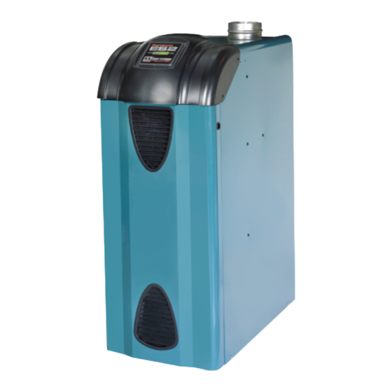
ES2™
ENHANCED SERIES 2
Gas - Fired Boiler
Boiler Serial Number
9700609
Installation Date
Phone Number
Price - $5.00
Advertisement
Table of Contents

Related Manuals for U.S. Boiler Company ENHANCED 2 Series


Summary of Contents for U.S. Boiler Company ENHANCED 2 Series
- Page 1 INSTALLATION, OPERATING AND SERVICE INSTRUCTIONS FOR ES2™ ENHANCED SERIES 2 Gas - Fired Boiler 9700609 For service or repairs to boiler, call your heating contractor. When seeking information on boiler, provide Boiler Model Number and Serial Number as shown on Rating Label. Boiler Model Number Boiler Serial Number Installation Date...
- Page 2 WARNINGS FOR ThE hOMEOWNER FOLLOW ALL INSTRUCTIONS and warnings DO NOT BLOCK OR OBSTRUCT flow of printed in this manual and posted on the boiler. combustion and ventilation air into or around the boiler. Insufficient air may cause the boiler to INSPECT THE BOILER ANNUALLY.
- Page 3 WARNINGS FOR ThE INSTALLER READ THIS ENTIRE MANUAL before attempting ADHERE TO ALL LOCAL CODE REQUIREMENTS. installation, start-up, or service. Improper 1. Installation must conform to requirements installation, adjustment, alteration, service, or of authority having jurisdiction or in the maintenance may cause serious property damage, absence of such requirements, with the personal injury, or death.
- Page 4 Congratulations on your purchase of a new ES2 boiler—designed and constructed to provide you with years of reliable service. • Cast iron heat exchanger – for reliability and durability, nothing beats a cast iron heat exchanger. • IQ Control™ System– the most advanced and easiest to use control available. • System-friendly –...
- Page 5 SPECIFICATIONS Ratings ES2 Series Net AHRI Rating, Water Input (MBH) DOE Heating Capacity (MBH) AFUE (%) Boiler Model (MBH) ES23 ES24 ES25 ES26 ES27 ES28 ES29 Input ratings can be used for elevations up to 2000 ft (600 m). Refer to Appendix F for elevations 2000 ft (600 m) or higher.
- Page 6 SPECIFICATIONS (continued) Weights and Volume Boiler Shipping Weight Empty Weight Water Content Model (lbs) (lbs) (gal) ES23 ES24 ES25 ES26 ES27 ES28 ES29 Figure S-1: Minimum Clearances to Combustible Materials...
-
Page 7: Table Of Contents
BOILER QUICk-START Installation: Unpack the crate ..................... 8 Position the boiler .................... 9 Provide combustion air .................. 10 Connect venting ..................... 10 Connect gas piping ..................11 Connect boiler water piping ................12 Connect electrical wiring ................13 Program the controls ..................14 Check for gas and water leaks .............. -
Page 8: Unpack The Crate
1. UNPACk ThE CRATE Tip the boiler and shimmy it off the skid THE BOILER IS TOP-HEAVY. Do not (Figure 1-b). allow it to tip over. Remove the sleeve. Remove the contents from the skid, except the boiler. Remove the four (4) hex-drive lag screws holding the boiler to the skid (Figure 1-a). -
Page 9: Position The Boiler
2. POSITION ThE BOILER WARNINGS OBSERVE MINIMUM CLEARANCES to CLEAN BURNERS DAILY if operating the boiler in combustible walls and ceilings to avoid potential a dusty environment. fire hazard. PROTECT IGNITION SYSTEM COMPONENTS DO NOT INSTALL ON CARPET. This may cause from sources of water that may spray, drip, or rain a fire. -
Page 10: Provide Combustion Air
3. PROVIDE COMBUSTION AIR Natural Gas and Propane Installation Code, CAN/ INSUFFICIENT COMBUSTION AIR CSA B149.1, or applicable provisions of the local SUPPLY may result in the production and building codes. release of deadly carbon monoxide (CO) into the home which can cause severe personal injury or death. -
Page 11: Connect Gas Piping
4. CONNECT VENTING (continued) DAMPER MUST BE OPEN POSITION when appliance main burner(s) is operating. Le registre doit être ouvert lorsque le brûleur principal de l’appareil fonctionne. 5. CONNECT GAS PIPING Size gas piping according to Appendix C – Gas nipples and street ells are not approved for Piping use as gas piping. -
Page 12: Connect Boiler Water Piping
6. CONNECT BOILER WATER PIPING General system piping guidelines are included in Screw the relief valve into manifold tapping Appendix D—System Piping. “RV”. Install with spindle vertical. Additionally, for this particular boiler install piping This installation is not complete until the shown below (Figure 6-a). -
Page 13: Connect Electrical Wiring
7. CONNECT ELECTRICAL WIRING DISCONNECT ELECTRICAL POWER to the boiler and heating system before servicing. Positively assure that no voltage is present. Lock electrical boxes to prevent someone from inadvertently restoring power before the heating system is safe to operate. NEVER DEFEAT OR JUMP OUT safety devices. -
Page 14: Program The Controls
8. PROGRAM ThE CONTROLS Using Intelligent Hydronic Control Display Viewing the Operating Mode Options In operating mode the user may view (but not The Intelligent Hydronic Control (control) is located change) boiler operating status, settings and inside the boiler front door, just above the IQ troubleshooting information. - Page 15 8. PROGRAM ThE CONTROLS (continued) More Information about Adjustable Parameters Unit Display 1 sec 1 sec High Limit (HL_) 1 sec The control is factory programmed with a Sample High Limit Setpoint of 180°F. The burner Display turns "off" when the boiler temperature (bt) is above this value.
- Page 16 8. PROGRAM ThE CONTROLS (continued) Circulator Pre-purge time has a factory Domestic Hot Water (DHW) Terminal setting of 2 minutes and is field adjustable Function (dh_) between 2 and 20 minutes. When reset card The control allows configuration of the is installed, pre-purge time may be adjusted DHW Circulator output functionality to help down to zero (0) minutes.
-
Page 17: Check For Gas And Water Leaks
8. PROGRAM ThE CONTROLS (continued) b. When dh_ is set equal to Second Heating Using the IQ Option Panel Zone (tt2) IQ Option Cards are available from U.S. Boiler When there is no IWH the “DHW Company distributors and are the simplest way Circulator”... -
Page 18: Perform Startup Checks And Adjustments
10. PERFORM STARTUP ChECkS AND ADjUSTMENTS FAILURE TO PERFORM THESE CHECKS of the boiler's combustion and safety systems may result in serious property damage, injury, or death. IF YOU SMELL GAS, STOP and repair the leak. Lighting the boiler when gas is leaking may cause explosion or fire. -
Page 19: Annual Maintenance Checklist
10. PERFORM STARTUP ChECkS AND ADjUSTMENTS (continued) Return high limit to the desired setting (see Check combustion in the vent stack and "Programming High Limit" in Section 8). record results in the spaces provided below. _____ CO (less than 7%) Check draft. - Page 20 ANNUAL MAINTENANCE ChECkLIST (continued) Equipment you will need: Hold burner at throat. Lift front of burner to clear orifice (Figure AM-1). The q Soft bristle brush burner that holds the pilot can only be q Bristle flue brush removed by first lifting the burner q Vacuum with brush attachment adjacent to its right.
- Page 21 ANNUAL MAINTENANCE ChECkLIST (continued) AM-2 Operating Instructions, VR8204 and VR8304 Gas Valves...
-
Page 22: Troubleshooting
TROUBLEShOOTING Before troubleshooting wiring diagram in Figures IW1 and IW2. Ensure that incoming 120 Vac power polarity The following pages contain trouble shooting is correct and that the boiler is properly tables for use in diagnosing control problems. grounded. Further, ensure that the control When using these tables the following should power supply is 24 VAC (minimum 18 VAC be kept in mind:... - Page 23 TROUBLEShOOTING (continued) Use Control Display ERR (error) Number To Direct Troubleshooting Efforts If the control detects an error it will flash “Err” (error) followed by a number. Use this number to identify the boiler problem and corrective action in the table below. If there is no Err display proceed to the next Section: Display Status...
- Page 24 TROUBLEShOOTING (continued) Use STA (status) Number To Guide Troubleshooting The control will flash “STA” followed by a number. Use this number to identify the boiler problem in the table below: 1. Boiler and Circulator Off Display / Status Recommended Corrective Action The boiler has not detected a call for heat (tt = off and dh = off).
- Page 25 TROUBLEShOOTING (continued) 5. Circulator is On But Damper is Not Open Display / Status Recommended Corrective Action The control is waiting for the damper to open. Damper end switch has failed to close (end switch contact is stuck open). Combustion can never take place unless the damper blade is in the fully open position. Check the following: - During status “STA18"...
- Page 26 TROUBLEShOOTING (continued) 6. Circulator is On, Damper is Open But Boiler Fails to Start (continued) Recommended Corrective Action Display / Status 1. No Spark a. Can you hear sparking while STA 6 is displayed? - If there is no spark noise replace the control. b.
- Page 27 TROUBLEShOOTING (continued) If Control Shows Status Code “STA 15": The control is “Waiting for Limit to Close” and the display on the IQ Option Panel should be the first place to check. The IQ Option Panel display (lower display) will show one of the following status codes: IQ Option Panel Display Shows “ERR"...
-
Page 28: Repair Parts List
All ES2™ Repair Parts may be obtained through your local U.S. Boiler Company Wholesale distributor. Should you require assistance in locating a U.S. Boiler Company Distributor in your area, or have questions regarding the availability of U.S. Boiler Company products or repair parts, please contact U.S. - Page 29 REPAIR PARTS LIST (continued) [Quantity] Part Number Description ES23 ES24 ES25 ES26 ES27 ES28 ES29 Base Wrapper 71807031 71807041 71807051 71807061 71807071 71807081 71807091 Base Tray 102543-03 102543-04 102543-05 102543-06 102543-07 102543-08 102543-09 Burner Tray Assembly 61807031 61807041 61807051 61807061 61807071 61807081 61807091...
- Page 30 REPAIR PARTS LIST (continued) [Quantity] Part Number Description ES23 ES24 ES25 ES26 ES27 ES28 ES29 Gas Valve (Natural Gas), 81660282 Honeywell VR8204P1171 Gas Valve (Natural Gas), 81660283 Honeywell VR8304P4496 Gas Valve (LP Gas), Honeywell 81660146 VR8204C3015 Gas Valve (LP Gas), Honeywell 81660160 VR8304P4314 ½"...
- Page 31 REPAIR PARTS LIST (continued) [Quantity] Part Number Description ES23 ES24 ES25 ES26 ES27 ES28 ES29 Control 103660-01 IQ Option Panel 102291-01 Transformer 102516-01 Temperature Sensor 102411-01 Temperature Sensor Spring Clip (not shown) 102422-01...
- Page 32 REPAIR PARTS LIST (continued) [Quantity] Part Number Description ES23 ES24 ES25 ES26 ES27 ES28 ES29 Jacket Left Side Panel 102566-01 Jacket Right Side Panel 102567-01 Jacket Rear Panel 102569-03 102569-04 102569-05 102569-06 102569-07 102569-08 102569-09 Jacket Vestibule Panel 102565-03 102565-04 102565-05 102565-06 102565-07 102565-08 102565-09 Jacket Top Panel 102568-03 102568-04 102568-05 102568-06 102568-07 102568-08 102568-09 Jacket Front Door...
- Page 33 REPAIR PARTS LIST (continued) [Quantity] Part Number Description ES23 ES24 ES25 ES26 ES27 ES28 ES29 Supply Water Manifold 80607001 Temperature/Pressure Gauge 100282-01 30 PSI Relief Valve 81660363 Drain Valve 102802-01 Vent Damper 102284-01 102284-02 102284-03 102284-04 102284-05 Circulator (not shown): Taco 007-2 8056170 Grundfos UP-15...
-
Page 34: Internal Wiring
INTERNAL WIRING Figure IW-1: Wiring Diagram... - Page 35 INTERNAL WIRING (continued) Figure IW-2: Wiring Schematic...
- Page 36 INTERNAL WIRING (continued) Figure IW-3: Multiple Zone System with Zone Circulators Figure IW-4: Multiple Zone System with Zone Valves...
- Page 37 INTERNAL WIRING (continued) Figure IW-5: Multiple Zone System with Zone Circulator Panel DHW AQUASTAT (L4006, L4080) POWER (SUPPLIED BY OTHERS) SUPPLY 120/60/1 THERMOSTAT THERMOSTAT THERMOSTAT TRANSFORMER DOMESTIC HOT WATER PRIORITY IS SELECTED USING ZONE PANEL SWITCH MODE ZONE 4 PRIORITY NORMAL RESET IQ OPTION PANEL POWER IN...
-
Page 38: A - Combustion Air
APPENDIX A – COMBUSTION AIR If the Floorspace from Step 1 is less than the PROVIDE ENOUGH AIR to ventilate the Minimum Floorspace from Step 3, then you boiler room, dilute the flue gases, and must provide outdoor air to the boiler room. sustain combustion. -
Page 39: B - Venting
APPENDIX B – VENTING VENT THIS BOILER according to the instructions. Failure to do so may cause products of combustion to enter the building resulting in severe property damage, personal injury or death. Install this boiler according to this manual and the National Fuel Gas Code, ANSI Z223.1/NFPA 54, the Natural Gas and Propane Installation Code, CAN/CSA B149.1, or applicable provisions of the local building codes. - Page 40 APPENDIX B – Venting (continued) Au moment du retrait d’une chaudière Une fois qu’il a été déterminé, selon existante, les mesures suivantes doivent la méthode indiquée ci-dessus, que être prises pour chaque appareil toujours chaque appareil raccordé au système raccordé au système d’evacuation d’évacuation est mis à...
- Page 41 APPENDIX B1 – ATMOSPhERIC VENTING GENERAL WARNINGS FOR ATMOSPhERIC VENTING SYSTEMS USE ATMOSPHERIC VENTING only with Exception: National Fuel Gas Code, boilers approved for atmospheric venting as ANSI Z223.1/ NFPA 54, and Natural Gas noted in the Specifications Section of this and Propane Installation Code, CAN/ manual.
- Page 42 APPENDIX B1 – Atmospheric Venting (continued) Install vent and vent connector (Figure B-1). Vent installation shall be in accordance with "Venting of Equipment," of the National Fuel Gas Code, ANSI Z223.1/NFPA 54, or "Venting systems and Air Supply for Appliances," of the Natural Gas and Propane Installation Code, CAN/CSA B149.1, or applicable provisions of the local building codes.
-
Page 43: C - Gas Piping
APPENDIX C – GAS PIPING Table C-3: Specific Gravity Correction Factors For ASSURE GAS PIPING IS LEAK FREE Natural Gas AND OF PROPER SIZE and type for the connected load. Specific Correction Specific Correction Gravity Factor Gravity Factor SHUT OFF MAIN GAS SUPPLY prior to installing or servicing boiler gas piping. -
Page 44: D - System Piping
APPENDIX C – Gas Piping (continued) Bond all above-ground gas piping to a When testing at ½ psig (3.5 kPa) or less, grounding electrode and ensure the piping is isolate boiler from gas supply piping by electrically continuous. closing boiler’s individual manual shut-off valve. - Page 45 APPENDIX D – System Piping (continued) Overpressure primary-secondary loop when needed to maintain water temperatures and flows Install a properly sized expansion tank. within the specified limits. Do not exceed the boiler’s specific (3) Do not allow chilled water to enter the requirements for maximum allowable boiler during the heating cycle, or heated working pressure.
- Page 46 APPENDIX D – System Piping (continued) The following system diagrams are intended to provide a minimum level of guidance for a successful and trouble-free installation of the boiler in common applications. They do not substitute for proper design, evaluation, and installation by a trained and qualified installer using the proper tools, techniques, and design expertise.
- Page 47 APPENDIX D – System Piping (continued)
-
Page 48: E - Filling The System And Checking For Leaks
APPENDIX E – FILLING ThE SYSTEM AND ChECkING FOR LEAkS Fill entire heating system with water and vent air from system. Use the following procedure on a Series Loop or multi-zoned system installed as per the Figures in Appendix D. Remove air from system when filling. -
Page 49: F - Adjusting Gas Input Rate
APPENDIX F – ADjUSTING GAS INPUT RATE Input ratings shown on boiler rating label can be used for elevations up to 2000 ft (600 m). United States. For elevations 2000 ft (600 m) or higher, reduce input rate 4 percent per 1000 ft (300 m) above sea level. - Page 50 Figure F-2). leak detection solution or an electronic leak detector. • Contact your U.S. Boiler Company wholesale distributor for alternate main Repair any leaks. burner orifices if outlet pressure is less than 3.2 inches water column or greater...
-
Page 51: G - Checking Draft And Combustion
APPENDIX G – ChECkING DRAFT AND COMBUSTION CHECK DRAFT (GAS BOILERS WITH DRAFT HOODS) After 5 minutes of main burner operation, Insofar as is practical, close all doors and test for spillage at the draft hood relief windows in the building. opening, using a lighted match, candle, Turn on all appliances not connected to the cigarette, etc. -
Page 52: H - Operation
APPENDIX h – OPERATION Boiler Sequence of Operation the cause of the problem. Table 5 provides a list of boiler status codes that are reported. NORMAL OPERATION Refer to the Troubleshooting Section for more The ES2 Boilers are equipped with an information. -
Page 53: I - Iq Control System
APPENDIX I – IQ CONTROL SYSTEM IQ Control System Overview • Ensures adequate heat and supply of domestic hot water. The “IQ Control System” consists of a control and an IQ Option Panel with optional “plug in” cards: • UL / CSA Listed or Recognized and tested as part of a complete system. - Page 54 APPENDIX I – IQ Control System (continued) IQ Outdoor Reset Option Card Kit: P/N 105648-01 Installing the IQ Outdoor Reset Option Card is the simplest way to maximize the efficiency of any ES2 Boiler. The IQ Outdoor Reset Card is a microprocessor- based control that regulates the water temperature of the heating system based on the outdoor temperature.
- Page 55 APPENDIX I – IQ Control System (continued) IQ Hi Limit Option Card (Auto Reset) Kit: P/N 102717-01 IQ Hi Limit Option Card (Manual Reset) Kit: P/N 102720-01 IQ High Limit Option Cards add auxiliary temperature limit-rated controls to ES2 Boilers. High Limit Option Cards plug into the IQ Option Panel and connect to a system-mounted probe with a single Molex connection.
- Page 56 APPENDIX I – IQ Control System (continued) stem Parts List Optional Components Part Number Item Description Outside Reset IQ Option Card, Domestic Hot Water Priority, for use with Option Control Panel, with Outside 105648-01 Air Temperature Sensor with 60 inch lead, Instructions, Unit Pack. No additional pipe fittings required. Contact Factory Outdoor Reset IQ Option Card, Domestic Hot Water Priority, for use with IQ Option Panel, less Sensor.
- Page 60 U.S. Boiler Company, Inc. P.O. Box 3020 Lancaster, PA 17604 1-888-432-8887 www.usboiler.net...
Need help?
Do you have a question about the ENHANCED 2 Series and is the answer not in the manual?
Questions and answers