U.S. Boiler Company V8H Series Installation, Operating And Service Instructions
Hide thumbs
Also See for V8H Series:
Table of Contents
Advertisement
Installation, Operating and Service Instructions for
V8H
Models:
• V8H3WEH
• V8H3WE
• V8H4WEH
• V8H4WE
• V8H5WEH
• V8H5WE
• V8H6WEH
• V8H6WE
• V8H7WEH
• V8H7WE
Manual Contents
1. Dimensional Description, Specification &
Dimensional Data . . . . . . . . . . . . . . . . . . . . . 4
2. Pre-installation . . . . . . . . . . . . . . . . . . . . . . . 8
3. Knock Down Boiler Assembly . . . . . . . . . . 10
4. Packaged Boiler Assembly . . . . . . . . . . . . 17
5. Water Boiler Piping & Trim . . . . . . . . . . . . . 21
7. Venting & Air Intake Piping . . . . . . . . . . . . 27
8. Electrical . . . . . . . . . . . . . . . . . . . . . . . . . . . 31
9. Oil Piping . . . . . . . . . . . . . . . . . . . . . . . . . . . 36
10. System Start-Up . . . . . . . . . . . . . . . . . . . . . 38
11. Operating . . . . . . . . . . . . . . . . . . . . . . . . . . . 41
12. Service and Maintenance . . . . . . . . . . . . . 51
13. Boiler Cleaning . . . . . . . . . . . . . . . . . . . . . 53
14. Troubleshooting . . . . . . . . . . . . . . . . . . . . . 55
15. Service Parts . . . . . . . . . . . . . . . . . . . . . . . 58
16. Burner Specifications . . . . . . . . . . . . . . . . 64
Appendix . . . . . . . . . . . . . . . . . . . . . . . . . . . . . 65
TO THE INSTALLER:
Affix these instructions adjacent to boiler.
TO THE CONSUMER:
Retain these instructions for future reference.
For service or repairs to boiler, call your heating contractor. When seeking information on boiler, provide
Boiler Model Number and Serial Number as shown on Rating Label.
110218-01 - 3/20
TM
Residential Water
• V8H3WE-T
• V8H4WE-T
• V8H5WE-T
• V8H6WE-T
• V8H7WE-T
Page
• Water Boiler
• Natural Draft
• Oil-Fired
9700609
Advertisement
Table of Contents

Related Manuals for U.S. Boiler Company V8H Series


Summary of Contents for U.S. Boiler Company V8H Series
-
Page 1: Table Of Contents
Installation, Operating and Service Instructions for • Water Boiler • Natural Draft • Oil-Fired Residential Water Models: • V8H3WEH • V8H3WE-T • V8H3WE • V8H4WEH • V8H4WE-T • V8H4WE • V8H5WEH • V8H5WE-T • V8H5WE • V8H6WEH • V8H6WE-T • V8H6WE •... - Page 2 Installation & Service Manual IMPORTANT INFORMATION - READ CAREFULLY All boilers must be installed in accordance with National, State and Local Plumbing, Heating and Electrical Codes and the regulations of the serving utilities. These Codes and Regulations may differ from this instruction manual. Authorities having jurisdiction should be consulted before installations are made.
- Page 3 Installation & Service Manual DANGER DO NOT store or use gasoline or other flammable vapors or liquids in the vicinity of this or any other appliance. WARNING Improper installation, adjustment, alteration, service or maintenance can cause property damage, personal injury or loss of life. Failure to follow all instructions in the proper order can cause personal injury or death. Read and understand all instructions, including all those contained in component manufacturers manuals which are provided with the boiler before installing, starting-up, operating, maintaining or servicing this boiler.
-
Page 4: Dimensional Data
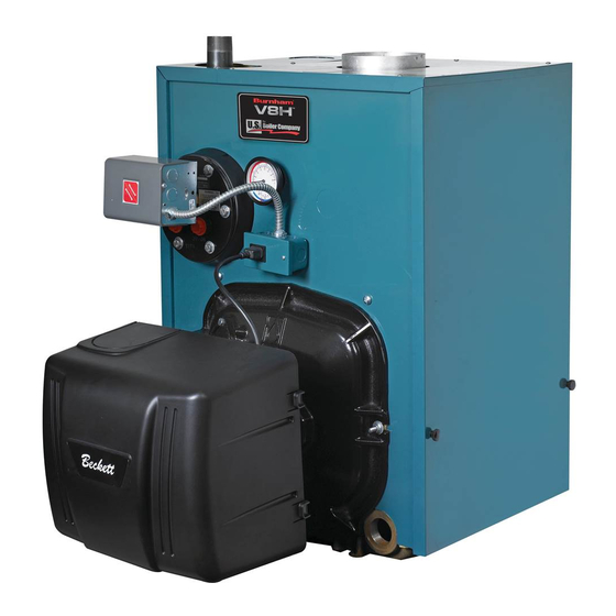
Be sure to tighten swing door fastener completely when service is completed. Product Description, Specification and Dimensional Data The V8H Series boiler is a cast iron oil-fired water Water Boilers boiler designed for closed forced circulation heating The V8H Series water boiler uses an Intelligent Oil systems. - Page 5 Installation & Service Manual Product Description, Specification and Dimensional Data (continued) Table 1A: Dimensional Data (See Figures 1A thru 1D) Dimensions See Fiures 1A thru 1D Approximate Water Content Boiler Series Shipping - Gallons "A" "B" "C" Weight (LB.) V8H3 17-1/8"...
- Page 6 Installation & Service Manual Product Description, Specification and Dimensional Data (continued) 110218-01 - 3/20...
- Page 7 Installation & Service Manual Product Description, Specification and Dimensional Data (continued) 110218-01 - 3/20...
-
Page 8: Pre-Installation
ANSI/NFPA 31 National Standard ANSI/NFPA 31, Installation standard. of Oil Burning Equipment. 2. V8H Series boilers can be installed in rooms with clearances from combustible material as listed above. Listed clearances cannot be reduced for alcove or closet installations. - Page 9 Installation & Service Manual Pre-Installation (continued) b. Outdoor air may be provided with the NOTICE Clearance to venting is for single wall use of two permanent openings which vent pipe. If Type L vent is used, clearance may communicate directly or by duct with the be reduced to the minimum required by the vent outdoors or spaces (crawl or attic) freely pipe manufacturer.
-
Page 10: Knock Down Boiler Assembly
Installation & Service Manual Knock Down Boiler Assembly A. REMOVAL OF BARE BOILER FROM SKID F. INSPECT FLUE COVER PLATES for tightness. If loose, retighten mounting hardware. If flue plate 1. Boiler is secured to skid with 4 bolts, 2 in front or sealing rope is damaged, repair or replace as and 2 in rear of shipping skid, see Figure 3. - Page 11 Installation & Service Manual Knock Down Boiler Assembly (continued) Figure 5: Boiler Tapping Locations and Usage (Knockdown Boilers Only) PURPOSE OF TAPPINGS Water Boiler Tapping Size Location Front Heater Non-Heater ¾" Boiler Control Boiler Control ¼" Temperature/Pressure Gauge ¾" ¾" ½"...
- Page 12 Installation & Service Manual Knock Down Boiler Assembly (continued) Figure 6: Knockdown Boiler Jacket Assembly INSTALL TRIM. The following water trim will be 3. The V8H5WE utilizes a combustion chamber concealed or inaccessible after boiler jacket is plate. To install, place the combustion chamber installed, see Figure 5 for boiler tapping locations plate in the center of the front section.
- Page 13 Installation & Service Manual Knock Down Boiler Assembly (continued) Figure 7: Oil Burner Installation (Beckett Burner Shown) for damage and adhesion. If damaged, 4. Install jacket left side panel. (See Figure 6, replace insulation or gasket. If insulation or Item 2E). Fold panel at perforation keeping gasket is loose, reattach to swing door with insulation inward.
- Page 14 Installation & Service Manual Knock Down Boiler Assembly mounted in return piping connected (continued) directly to 1½" NPT boiler return tapping "G", NOTICE When securing burner swing door make use the piping arrangements outlined in steps sure door is drawn-in equally on both sides. a.
- Page 15 Installation & Service Manual Knock Down Boiler Assembly (continued) See Figures 1A and 5. Tighten the well and 7. Connect Field Wiring. fully insert limit sensor into immersion well a. Water boilers without tankless heater. such that the tip on the limit sensor touches the Connect the field wiring to the aquastat bottom of the immersion well.
- Page 16 Installation & Service Manual Knock Down Boiler Assembly (continued) Figure 10: Burner Disconnect Junction Box with Power Outlet Receptacle (Mated to Burners with Disconnect Harness) 110218-01 - 3/20...
-
Page 17: Packaged Boiler Assembly
Installation & Service Manual Packaged Boiler Assembly Step 1. Loosen and remove right side latching A. REMOVE CRATE. hardware (5/16" flange nut and washer). 1. Remove all fasteners at crate skid. Step 2. Loosen and remove left side hinge 2. Lift outside container and remove all other hardware (5/16"... - Page 18 Installation & Service Manual Packaged Boiler Assembly (continued) Figure 12A: Partial Front View - Burner Swing Door Mounted to Boiler - Fully Closed and Secured NOTICE When securing burner swing door make F. INSTALL COMBUSTION CHAMBER RING/ sure door is drawn-in equally on both sides. PLATE.
- Page 19 Installation & Service Manual Packaged Boiler Assembly (continued) 110218-01 - 3/20...
- Page 20 Installation & Service Manual Packaged Boiler Assembly (continued) Figure 12C: Top View - Burner Swing Door Fully Closed but Not Properly Secured or Sealed 110218-01 - 3/20...
-
Page 21: Water Boiler Piping & Trim
The use of a low water cut-off device, while not required unless radiation level is below the U.S. Boiler Company recommends sizing boiler, is highly recommended. the system circulator to supply sufficient flow (GPM) to allow a 20°F temperature 5. - Page 22 Installation & Service Manual Water Boiler Piping and Trim (continued) To perform a long term pressure test including the boiler, ALL trapped air must first be removed from the boiler. A loss of pressure during such a test, with no visible water leakage, is an indication that the boiler contained trapped air.
- Page 23 Installation & Service Manual Water Boiler Piping and Trim (continued) 110218-01 - 3/20...
- Page 24 Installation & Service Manual Water Boiler Piping and Trim (continued) 110218-01 - 3/20...
-
Page 25: Tankless & Indirect Water Heater Piping
Installation & Service Manual Tankless and Indirect Water Heater Piping 3. FLUSHING OF HEATER — All water A. CONNECT TANKLESS HEATER PIPING as contains some sediment which settles on the shown in Figure 16. See Table 2 for Tankless inside of the coil. Consequently, the heater Heater Rating. - Page 26 Installation & Service Manual Tankless and Indirect Water Heater Piping (continued) Figure 16: Schematic Tankless Heater Piping Table 2: Tankless Heater Data: Front Mounted Heater on Water Boilers Pressure Drop Boiler Heater Heater Rating thru Heater Series (GPM) (PSI) V8H3 222B 3.00 18.7...
-
Page 27: Venting & Air Intake Piping
Installation & Service Manual Venting and Air Intake Piping WARNING Vent this boiler according to these instructions. Failure to do so may cause products of combustion to enter the home resulting in severe property damage, personal injury or death. • Insufficient Combustion Air Supply may result in the production and release of deadly carbon monoxide (CO) into the home which can cause severe personal injury or death. - Page 28 Installation & Service Manual Venting and Air Intake Piping (continued) Figure 17: Recommended Vent Pipe Arrangement and Chimney Requirements Figure 18: Proper and Improper Locations of Draft Regulator 110218-01 - 3/20...
- Page 29 Installation & Service Manual Venting and Air Intake Piping (continued) b. Steel pipe having resistance to corrosion d. Clean Chimney – Chimney shall be free of all and heat with a minimum wall thickness of loose debris. 24 Gauge (0.024”). 5.
- Page 30 Installation & Service Manual Venting and Air Intake Piping (continued) STACK TEMPERATURE 1. The temperature of the flue gases has a significant effect on the amount of draft created in a vertical chimney as well as the propensity to create condensate.
-
Page 31: Electrical
Installation & Service Manual Electrical 7. Wiring should conform to Figures 20A through DANGER Positively assure all electrical connections are B. INSTALL A ROOM THERMOSTAT on an inside unpowered before attempting installation or wall about four feet above floor. Never install service of electrical components or connections thermostat on an outside wall or where it will be of the boiler or building. - Page 32 Installation & Service Manual Electrical (continued) 110218-01 - 3/20...
- Page 33 Installation & Service Manual Electrical (continued) 110218-01 - 3/20...
- Page 34 Installation & Service Manual Electrical (continued) 110218-01 - 3/20...
- Page 35 Installation & Service Manual Electrical (continued) CARLIN PRIMARY Figure 21: Schematic Wiring Diagrams For All Burner Options w/Various Oil Primary Controls 110218-01 - 3/20...
-
Page 36: Oil Piping
Installation & Service Manual Oil Piping A. GENERAL WARNING 1. Use flexible oil line(s) so the burner swing door can be opened without disconnecting the oil Under no circumstances can copper with sweat supply piping. style connectors be used. 2. A supply line fuel oil filter is recommended as a NOTICE Some jurisdictions require the use of a minimum for all firing rates but a pleated paper fusible shutoff valve at the tank and/or the burner. - Page 37 Installation & Service Manual Oil Piping (continued) C. TWO PIPE OIL LINES Table 4: Single-Stage Units (3450 RPM) - Two Pipe Systems 1. For two piped systems, where more lift is required, the two-stage fuel unit is Maximum Length of Tubing recommended.
-
Page 38: System Start-Up
Installation & Service Manual System Start-Up WARNING All boilers equipped with burner swing door have a potential hazard which can cause severe property damage, personal injury or loss of life if ignored. Before opening swing door, turn off service switch to boiler to prevent accidental firing of burner outside the combustion chamber. - Page 39 Installation & Service Manual System Start-Up (continued) b. Locate oil pressure adjusting screw and 3. WATER BOILERS WITHOUT TANKLESS turn screw to obtain proper pump pressure, HEATERS are equipped with an Intelligent refer to Table 12 at the rear of this manual. Oil Boiler Control (Boiler Control).
- Page 40 Installation & Service Manual System Start-Up (continued) 2. VERIFY OIL PRIMARY CONTROL WARNING FEATURES using procedures outlined DO NOT attempt to start the burner when in Instructions furnished with control or excess oil has accumulated, when the boiler is instructions provided with burner. full of vapor, or when the combustion chamber 3.
-
Page 41: Operating
Installation & Service Manual Operating A. WATER BOILERS SEQUENCE OF OPERATION 1. Water Boilers Without Tankless Heaters (Cold Start), Sequence Of Operation: a. The V8H Boiler is equipped with a Cold Start Intelligent Oil Boiler Control (Cold Start Boiler Control). The Cold Start Boiler Control replaces the traditional electronic aquastat and circulator relays and adds energy saving thermal purge features. - Page 42 Installation & Service Manual Operating (continued) enter into restricted mode. Restricted mode thermostat is satisfied. Optionally, the is reset by holding down the reset button for thermal purge (circulator pre-purge time) 15 seconds. maybe added adjusting the Circulator 3. Using Cold or Warm Start Boiler Control Pre-purge time parameter.
- Page 43 Installation & Service Manual Operating (continued) (P) will equal the High Limit Setpoint. 5. Changing the Adjustable Parameters To adjust parameters such as the High Limit b. High Limit Differential (HdF) Setpoint and High Limit Differential: The Cold Start Boiler Control is factory a.
- Page 44 Installation & Service Manual Operating (continued) Table 6: Circulator Pre-Purge Time Example, Table 7: Domestic Hot Water Demand, Parameter PP_= 2 Minutes (Parameter ZC_= DH) ZC and ZR Call for Heat Circulator Status Call for Terminal Boiler Boiler Status, Priority System Function (B1 Output)
- Page 45 Installation & Service Manual Operating (continued) Table 8: Zone Request, Parameter zc_= zr Table 9: External Low Limit, Parameter zc_= ell Call for Heat Circulator Status Call for Heat Circulator Status Input Input Output Output Input Input Output Output When ZC_ is set equal to Zone Request terminal is energized.
- Page 46 Installation & Service Manual Operating (continued) IMPORTANT: If low limit temperature cannot be set This feature works with single-zone above 140oF, remove jumper B. (Setting range: OFF or and multi-zone heating systems utilizing circulators or zone valves. No change in 110o -200o F).
- Page 47 Installation & Service Manual Operating (continued) WARNING: DO NOT ADD WATER UNTIL THE • Reset LO TEMP and HI TEMP settings to BOILER HAS FULLY COOLED. desired temperatures. To activate Manual Reset LWCO mode Setting the Well Type (Elctro-Well vs. •...
- Page 48 Installation & Service Manual Operating (continued) Default Dial Setting Feature Options Description Setting Purge Inactive Thermal Pre-Pruge Purge Active Degrees Fahrenheit Fahrenheit or Celsius Degree Celcius LWCO Manual or Automatic Reset Automatic Reset Manual Reset Circulator operation on TT call only Circulator Options Circulator operation on ZC/ZR call only Circulator operation on call from either...
- Page 49 Installation & Service Manual Operating (continued) LWCO TEST LCO WARNING The red Low Water light should illuminate and the Allow the boiler to fully cool before adding water. burner circuit (B1 and B2) should de-energize. NOTE: The control must be installed with a Hydrolevel e.
- Page 50 Installation & Service Manual Operating (continued) Important Product Safety Information: Refractory Ceramic Fiber Product WARNING Some boiler components contain refractory ceramic fibers (RCF). RCF has been classified as a possible human carcinogen. When exposed to temperatures above 1805°F, such as during direct flame contact, RCF changes into crystalline silica, a known carcinogen.
-
Page 51: Service And Maintenance
Installation & Service Manual Maintenance and Service Instructions i. Apply a moderate amount of good quality A. MAINTENANCE OF LOW WATER CUT-OFF DEVICES pipe dope to the pipe threads on the probe, leaving the two end threads bare. DO NOT WARNING use PTFE (Teflon) tape. - Page 52 Installation & Service Manual Maintenance and Service Instructions (continued) ix. Continue to circulate the water for a few A leaky system will increase the volume of hours. make-up water supplied to the boiler which can significantly shorten the life of the boiler. Entrained x.
-
Page 53: Boiler Cleaning
Installation & Service Manual Boiler Cleaning WARNING All boiler cleaning must be completed with burner service switch turned off. Boilers equipped with burner swing door have a potential hazard which can cause severe property damage, personal injury or loss of life if ignored. - Page 54 Installation & Service Manual Boiler Cleaning (continued) Figure 27: Cleaning of Boiler Flueways WARNING The boiler must be connected to an approved chimney in good condition. Serious property damage could result if the boiler is connected to a dirty or inadequate chimney. The interior of the chimney flue must be inspected and cleaned before the start of the heating season and should be inspected periodically throughout the heating season for any obstructions.
-
Page 55: Troubleshooting
Installation & Service Manual Troubleshooting A. COMBUSTION nozzle. The smaller the firing rate, the smaller the slots become in the nozzle and the more 1. NOZZLES — Although the nozzle is a relatively prone to plugging it becomes with the same inexpensive device, its function is critical to amount of dirt. - Page 56 Installation & Service Manual Troubleshooting (continued) 3. Control locks out after Trial For Ignition (TFI). NOTICE CHECK TEST PROCEDURE. A very good test for isolating fuel side problems is to disconnect the a. No oil to burner. fuel system and with a 24" length of tubing, fire out of b.
- Page 57 Installation & Service Manual Troubleshooting (continued) a. If an Error Code "Err" IS NOT displayed on the Boiler Control: In this circumstance, Table 10 can be used to determine the problem and possible causes. b. If the Boiler Control detects an error it will flash "Err"...
- Page 58 Installation & Service Manual Page Intentionally Left Blank 110218-01 - 3/20...
-
Page 59: Service Parts
Installation & Service Manual Service Parts All V8H™ Series Boiler Service Parts may be obtained through your local U.S. Boiler Company Wholesale distributor. Should you require assistance in locating a U.S. Boiler Company Distributor in your area, or have questions regarding the availability of U.S. - Page 60 Installation & Service Manual Service Parts (continued) 110218-01 - 3/20...
- Page 61 Installation & Service Manual Service Parts (continued) Item Description Part Number V8H3WE V8H4WE V8H5WE V8H6WE V8H7WE 101349-03 WF: Block Assembly Carton for Water, Front 101349-04 Heater Opening Includes: Complete Block 101349-05 Assembly, Target Wall Insulation, Flue Cover 101349-06 Plates, Coil Gasket, Coil Cover Plate/ Hardware 610280711 101362-03 101362-04...
- Page 62 Installation & Service Manual Repair Parts (continued) Water Boilers - Trim and Controls 110218-01 - 3/20...
- Page 63 Installation & Service Manual Repair Parts (continued) Item No. Description Part Number V8H3WE V8H4WE V8H5WE V8H6WE V8H7WE 110270-03 110270-04 WF: Complete Jacket Carton for Water, Front 110270-05 Heater 110270-06 110270-07 110271-03 110271-04 WN: Complete Jacket Carton for Water, Non- 110271-05 Heater 110271-06 110271-07...
- Page 64 Installation & Service Manual Service Parts (continued) Item No. Description Part Number V8H3WE V8H4WE V8H5WE V8H6WE V8H7WE 110222-03 110223-04 Beckett 110224-05 110225-06 102114-07 101292-01 101293-01 Carlin 101294-01 101295-01 101296-01 Shown 101307-01 101308-01 Riello 101309-01 101310-01 101311-01 Honeywell R7284P1080 103880-01 Beckett GeniSys 7505P1515 Primary Obtain Locally Carlin...
-
Page 65: Burner Specifications
Installation & Service Manual Burner Specifications Table 12: Burner Specifications Beckett AFG Carlin Firing Boiler Settings Nozzle Settings Nozzle Rate Pump Burner Pump Model Head GPH x Angle GPH x Pressure Model Pressure Head Bar (Setting) Shutter Band Type Band Angle Type V8H3WE 1.00... - Page 66 Installation & Service Manual Appendix A - Aftermarket Low Water Cut Off (LWCO) WARNING DO NOT ATTEMPT to cut factory wires to install an aftermarket Low Water Cut Off (LWCO). Only use connections specifically identified for Low Water Cut Off. In all cases, follow the Low Water Cut Off (LWCO) manufacturer's instructions.
- Page 67 Installation & Service Manual Appendix A - Aftermarket Low Water Cut Off (LWCO) How to Test A 24 VAC LWCO is used primarily for gas fired Shut off fuel supply. Lower water level until water boilers where a 24 volt control circuit exists within level is BELOW the LWCO.
- Page 68 Installation & Service Manual U.S. Boiler Company, Inc. P.O. Box 3020 Lancaster, PA 17604 1-888-432-8887 www.usboiler.net 110218-01 - 3/20...
Need help?
Do you have a question about the V8H Series and is the answer not in the manual?
Questions and answers