Advertisement
Advertisement
Table of Contents

Related Manuals for Nvidia P1453


Summary of Contents for Nvidia P1453
- Page 1 P1453 3D Vision Pro Embedded Hub Manual Last Update: 5/22/12 Page 1 of 10...
-
Page 2: Table Of Contents
Table of Contents Getting to Know the P1453 _____________________________________________________________________ Requirements System ___________________________________________________________________________ Installation Guide ______________________________________________________________________________ Product Specicification _________________________________________________________________________ Regulatory Compliance Statement ______________________________________________________ 9 Last Update: 5/22/12 Page 2 of 10... -
Page 3: Getting To Know The P1453
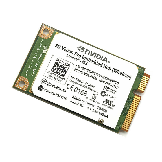
The following figure shows the appearance of the P1453. The actual product may differ. ① Mini PCI Express connector It is used to connect the P1453 to the WWAN Mini PCI Express interface of the PC. ② Screw holes They are used to fix the P1453 on the main board of the PC with screws. -
Page 4: System Requirements
System Requirements Before you begin, please review the following minimum system requirements to ensure your Laptop meets the hardware requirements necessary to enjoy the 3D Vision experience. 1) Microsoft Windows Vista 32/64‐bit or Windows 7 32/64‐bit 2) 3D‐capable display 3) NVIDIA graphics cards Last Update: 5/22/12 Page 4 of 10... -
Page 5: Installation Guide
PC. 2. Press downwards to fix the P1453 in the module slot. 3. Use a screwdriver to fix the P1453 onto the main board of the PC with two screws provided in the P1453 packing box. Last Update: 5/22/12... - Page 6 4. Insert the connector of the main antenna into the MAIN antenna interface (M) of the P1453 according to the indication on the label of the P1453. Note: Insert the antenna connectors vertically into the antenna interfaces of the P1453.
- Page 7 3. Slide backwards the two clips to release the P1453 from the slot. Then, lift up the P1453. Installing the P1453 Software The driver of P1453 is included in NVIDIA graphics driver; you can down load the driver from http://www.nvidia.com/page/home.html 1, Double click the driver to run the program 2.
-
Page 8: Product Specicification
Technical Specification: 1.1. Power Input: DC 3.3V @140mA 1.2. Transmission mode: RF 1.3. Frequency: 2406~2473 MHz 1.4. RF channel quantity: 68 1.5. Center of Channel: 2406MHz /2407MHz/2408M…2472MHz/2473MHZ 1.6. Channel Interval: 1MHz Width of Channel: ≤1.0MHz 1.7. 1.8. Data Rate: <1Mbps 1.9. -
Page 9: Regulatory Compliance Statement
End Product Labelling The final end product must be labelled in a visible area with the following: “Contains FCC ID: VOB-P1453” Manual Information to the End User The OEM integrator has to be aware not to provide information to the end user regarding how to install or remove this RF module in the user’s manual of the end product which integrates this module. - Page 10 Because of this, NVIDIA recommends that the user limits the output power to 10mW (10dBm) for Europe to avoid having to deal with the local authorities for spectrum management of each relevant member state Caution: Exposure to Radio Frequency Radiation.
Need help?
Do you have a question about the P1453 and is the answer not in the manual?
Questions and answers