Table of Contents
Advertisement
Quick Links
Advertisement
Table of Contents

Related Manuals for Siemens SIPROTEC 5 Compact


Summary of Contents for Siemens SIPROTEC 5 Compact
- Page 1 Preface Table of Contents Introduction Forms of Devices and On-Site Operation SIPROTEC 5 Compact Panels Hardware Description Electronic Modules Communication V8.83 and higher Working on the Device Manual Technical Data Ordering Information Literature Glossary Index C53000-G5300-C002-3...
- Page 2 Document version: C53000-G5300-C002-3.03 Trademarks Edition: 12.2021 SIPROTEC, DIGSI, SIGRA, SIGUARD, SIMEAS, SAFIR, SICAM, Version of the product described: V8.83 and higher and MindSphere are trademarks of Siemens. Any unauthor- ized use is prohibited.
-
Page 3: Preface
Preface Purpose of the Manual This manual describes the hardware of the SIPROTEC 5 Compact device family and provides general informa- tion on the product structure, the modules and technical data. Target Audience Protection system engineers, commissioning engineers, persons entrusted with the setting, testing and main- tenance of automation, selective protection and control equipment, and operational crew in electrical installa- tions and power plants. - Page 4 EN 61000-6-2 and EN 61000-6-4 (for EMC directive), the standard EN 50581 (for RoHS directive), and with the product standard EN 60255-27 (for Low Voltage Directive) by Siemens. The device is designed and manufactured for application in an industrial environment.
- Page 5 Preface IND. CONT. EQ. 69CA Additional Support For questions about the system, contact your Siemens sales partner. Customer Support Center Our Customer Support Center provides a 24-hour service. Siemens AG Smart Infrastructure – Digital Grid Phone: +49 911 2155 4466...
- Page 6 Selection of Used Symbols on the Device Symbol Description Direct current, IEC 60417, 5031 Alternating current, IEC 60417, 5032 Direct and alternating current, IEC 60417, 5033 Earth (ground) terminal, IEC 60417, 5017 SIPROTEC 5 Compact, Hardware Description, Manual C53000-G5300-C002-3, Edition 12.2021...
- Page 7 This product includes software developed by the OpenSSL Project for use in OpenSSL Toolkit (http:// www.openssl.org/). This product includes software written by Tim Hudson (tjh@cryptsoft.com). This product includes cryptographic software written by Eric Young (eay@cryptsoft.com). SIPROTEC 5 Compact, Hardware Description, Manual C53000-G5300-C002-3, Edition 12.2021...
- Page 8 SIPROTEC 5 Compact, Hardware Description, Manual C53000-G5300-C002-3, Edition 12.2021...
-
Page 9: Table Of Contents
Table of Contents Preface................................3 Introduction..............................11 Advantages of SIPROTEC 5 Compact.................. 12 Hardware Features......................15 Forms of Devices and On-Site Operation Panels..................17 Device Design........................18 2.1.1 General Description ....................18 2.1.2 Description ......................... 23 Surface-Mounted Devices....................26 2.2.1 Description........................26 Integrated Interfaces......................27 Terminals..........................28... - Page 10 Integrated Ethernet Interface.................... 60 Design Data........................61 Assembly Dimensions....................... 63 Ordering Information..........................67 Ordering Spare Parts and Accessories................68 7.1.1 Order Configurator and Order Options................. 68 7.1.2 Accessories........................68 Literature..............................69 Glossary..............................71 Index................................73 SIPROTEC 5 Compact, Hardware Description, Manual C53000-G5300-C002-3, Edition 12.2021...
-
Page 11: Introduction
Introduction Advantages of SIPROTEC 5 Compact Hardware Features SIPROTEC 5 Compact, Hardware Description, Manual C53000-G5300-C002-3, Edition 12.2021... -
Page 12: Advantages Of Siprotec 5 Compact
1.1 Advantages of SIPROTEC 5 Compact Advantages of SIPROTEC 5 Compact Thanks to the modular design of the software as well as the functional integration, SIPROTEC 5 Compact devices are well suited for all tasks in the energy sector. The devices include: •... - Page 13 A common function library provides all protection, automation, monitoring, and auxiliary functions for the SIPROTEC 5 Compact devices. The same functions are truly the same for all devices. Once established, configu- rations can be transferred from device to device. This results in substantially reduced engineering effort.
- Page 14 Introduction 1.1 Advantages of SIPROTEC 5 Compact • User-friendly operation panel – 9 freely assignable function keys for frequently required operator control actions – Separate control keys for switching commands – Simple switchover of the switching authority – Context-sensitive keys with labeling in the display –...
-
Page 15: Hardware Features
Optionally, the module can include an additional input and output module IO060 for extra binary inputs and outputs. SIPROTEC 5 Compact is also equipped with a redundant optical Ethernet interface. SIPROTEC 5 Compact, Hardware Description, Manual... - Page 16 SIPROTEC 5 Compact, Hardware Description, Manual C53000-G5300-C002-3, Edition 12.2021...
-
Page 17: Forms Of Devices And On-Site Operation Panels
Forms of Devices and On-Site Operation Panels Device Design Surface-Mounted Devices Integrated Interfaces Terminals SIPROTEC 5 Compact, Hardware Description, Manual C53000-G5300-C002-3, Edition 12.2021... -
Page 18: Device Design
Figure 2-1 SIPROTEC 5 Compact – Functional Integration – Control SIPROTEC 5 Compact includes all control and supervision function at bay level, required for an efficient opera- tion of the switchgear. The , freely configurable, color graphic display for control diagrams is available for convenient local control. - Page 19 • Automatic grid separations in the event of grid stability problems Of course, SIPROTEC 5 Compact provides a substation automation system, such as SICAM PAS/PQS, with all necessary information, thus ensuring consistent, integrated, and efficient solutions for further automation. Using macros makes it possible to reuse CFC subplans simply and clearly, in the device, project, or in other projects.
- Page 20 Monitoring power quality Self-Monitoring SIPROTEC 5 Compact devices are equipped with many monitoring procedures. These detect faults, internal as well as external, in secondary circuits, store them in buffers, and report them. This information is used to record the device fault and helps to determine the cause of the error in order to take appropriate corrective actions.
- Page 21 PQ status for the entire power system since all the installed SIPROTEC 5 Compact devices can simply be upgraded via a firmware update without having to install addi- tional hardware. You can then, for example, perceive trends and be warned if the power quality has reached problematic limits at sensitive points.
- Page 22 Figure 2-4 SIPROTEC 5 Compact – Functional Integration – Communication SIPROTEC 5 Compact devices are equipped with high-performance communication interfaces. These are inte- grated interfaces to provide a high level of security and flexibility. The interface is independent of the protocol used.
-
Page 23: Description
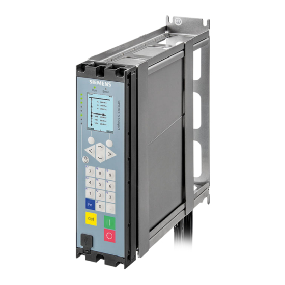
Description 2.1.2 SIPROTEC 5 Compact Design The SIPROTEC 5 Compact device is 1/6 x 19 inches wide. The on-site operation panel features a graphical color display, keyboard, and 8 dual color LEDs. SIPROTEC 5 Compact, Hardware Description, Manual C53000-G5300-C002-3, Edition 12.2021... - Page 24 8 additional LEDs, to the left of the keypad, ensure quick, targeted process feedback. The LED labeling is directly shown on the display. The USB interface enables fast data transmission. It is easily accessible from the front and well protected with a plastic cover. SIPROTEC 5 Compact, Hardware Description, Manual C53000-G5300-C002-3, Edition 12.2021...
- Page 25 The O and I keys (red and green) for the direct control of equipment, a key for displaying the LED labeling, and the CTRL key for activating the system diagram complete the operation panel. You can order any SIPROTEC 5 Compact device in 2 different installation variants: •...
-
Page 26: Surface-Mounted Devices
Description 2.2.1 A surface-mounting frame for the SIPROTEC 5 Compact device can be ordered as an accessory to install it on the wall. Thanks to a new concept, these devices thus have terminal connection diagrams that are identical to the corresponding flush-mounting devices. With the distance frames that are used, sufficient space remains for the wiring, which can be routed away upward and downward. -
Page 27: Integrated Interfaces
The maximum optically permitted distance via 50/125-µm or 62.5/125-µm multimode optical fibers is 2 km. The optical transmission and receiving level is measured in the module and can be displayed with DIGSI 5. In preparation SIPROTEC 5 Compact, Hardware Description, Manual C53000-G5300-C002-3, Edition 12.2021... -
Page 28: Terminals
Forms of Devices and On-Site Operation Panels 2.4 Terminals Terminals SIPROTEC 5 Compact Terminals Innovative terminals were developed for the SIPROTEC 5 Compact family. All terminals are individually remov- able (Figure 2-10). This enables prewiring of the systems and simple device replacement without costly rewiring. - Page 29 The binary input and output signals are connected via this 19-pole screw terminal. Where contacts can be connected to common potential of contacts, 1 wire jumper must also be connected in addition to the connec- tion wire. Observe the overall connection cross-section. SIPROTEC 5 Compact, Hardware Description, Manual C53000-G5300-C002-3, Edition 12.2021...
- Page 30 Forms of Devices and On-Site Operation Panels 2.4 Terminals [dw_terminal_block_standard, 1, --_--] Figure 2-12 Industry Standard Terminal SIPROTEC 5 Compact, Hardware Description, Manual C53000-G5300-C002-3, Edition 12.2021...
-
Page 31: Electronic Modules
Electronic Modules Power-Supply Module PS050 Input and Output Module IO060 SIPROTEC 5 Compact, Hardware Description, Manual C53000-G5300-C002-3, Edition 12.2021... -
Page 32: Power-Supply Module Ps050
DC 24 V to 250 V and AC 100 V to 230 V (50 Hz and 60 Hz) Terminals 3.1.2 Overview of Terminals [sv_PS050, 1, en_US] Figure 3-1 PS050 – Connection Diagram SIPROTEC 5 Compact, Hardware Description, Manual C53000-G5300-C002-3, Edition 12.2021... -
Page 33: Input And Output Module Io060
10 binary inputs • 6 binary outputs (fast make contacts, type F) The connections are on: • 1 x 19-pole voltage terminal NOTE Binary inputs that are not used must be grounded. SIPROTEC 5 Compact, Hardware Description, Manual C53000-G5300-C002-3, Edition 12.2021... -
Page 34: Terminals
Electronic Modules 3.2 Input and Output Module IO060 Terminals 3.2.2 Overview of Terminals [dw_IO060, 1, en_US] Figure 3-2 IO060 – Connection Diagram SIPROTEC 5 Compact, Hardware Description, Manual C53000-G5300-C002-3, Edition 12.2021... -
Page 35: Communication
Communication Integrated Interfaces SIPROTEC 5 Compact, Hardware Description, Manual C53000-G5300-C002-3, Edition 12.2021... -
Page 36: Integrated Interfaces
Integrated Interfaces on the Rear Panel of the Device SIPROTEC 5 Compact provides a permanently installed redundant Ethernet interface on the rear panel. For this, observe the connection plans in the chapters 3.1.2 Terminals 3.2.2... - Page 37 Ensure that you route the communication lines separately from network circuits. [le_SIP5Comp_communication_ports, 1, --_--] Figure 4-1 SIPROTEC 5 Compact Communication Connections Protective grounding terminal Integrated redundant Ethernet interface F Serial interface/IRIG-B time synchronization E (under development) SIPROTEC 5 Compact, Hardware Description, Manual C53000-G5300-C002-3, Edition 12.2021...
- Page 38 SIPROTEC 5 Compact, Hardware Description, Manual C53000-G5300-C002-3, Edition 12.2021...
-
Page 39: Working On The Device
Working on the Device First Steps Battery Installing Current and Voltage Terminals SIPROTEC 5 Compact, Hardware Description, Manual C53000-G5300-C002-3, Edition 12.2021... -
Page 40: First Steps
Close the battery compartment on the bottom of the device. ² Grounding a Device All SIPROTEC 5 Compact devices, are protection class I equipment and must be connected to the system ground prior to commissioning. Ground each module with solid low-impedance system grounding (cross-section ≥ 4.0 mm (≥... - Page 41 After (initial) activation, there is no Device Configuration File (DCF) in the device and the device is in fall- back mode. The green and red LEDs light in fallback mode. Once you have loaded the DCF file into the SIPROTEC 5 Compact device, the green RUN LED lights up ²...
-
Page 42: Battery
The device cyclically checks the charge of the battery. The Battery fault indication is issued if the actual voltage falls below the minimum. [le_SIP5Comp_battery_position, 1, --_--] Figure 5-1 Position of the Battery Compartment on the SIPROTEC 5 Compact Device Battery compartment Insulating film Replacing the Battery 5.2.2... - Page 43 ² Grab the tab of the battery slide with small flat nose pliers and lift it over the 2 battery retaining tabs. ² Slide the battery slide further over the battery. SIPROTEC 5 Compact, Hardware Description, Manual C53000-G5300-C002-3, Edition 12.2021...
-
Page 44: Environmental Protection Hints
When disposing of or transferring a mobile storage device, Siemens strongly recommends physically destroying it or completely deleting data from the mobile storage device by using a commercially available computer data erasing software. - Page 45 REACH/RoHS Declaration You can find our current REACH/RoHS declarations at: https://www.siemens.com/global/en/home/products/energy/ecotransparency/ecotransparency-down- loads.html NOTE You can find more information about activities and programs to protect the climate at the EcoTransparency website: https://www.siemens.com/global/en/home/products/energy/ecotransparency.html SIPROTEC 5 Compact, Hardware Description, Manual C53000-G5300-C002-3, Edition 12.2021...
-
Page 46: Installing Current And Voltage Terminals
Instrument transformers are transformers with a rated current of 1 A or 5 A and a measuring range of 1.6 x rated current. Instrument transformers are also referred to as sensitive protection-class current trans- formers or sensitive ground-current transformers. SIPROTEC 5 Compact, Hardware Description, Manual C53000-G5300-C002-3, Edition 12.2021... - Page 47 Terminal Designations The current terminals have different designations in DIGSI, the configurator, and the device. The following table provides an overview of the different terminal designations and order numbers of the terminals. SIPROTEC 5 Compact, Hardware Description, Manual C53000-G5300-C002-3, Edition 12.2021...
-
Page 48: Connections Of Current Terminals
Stranded-wire conductor with ring-type lug • Stranded-wire conductor with bootlace ferrule • Solid conductor Siemens recommends the use of ring-type lugs with the dimensions shown in the following figure. Use copper cables only. [dwringka-030211-01.tif, 1, en_US] Figure 5-9 Ring-Type Lug D (for bolt) 5.0 mm (0.2 in) - Page 49 Always guide the solid conductor or stranded-wire conductor with bootlace from the left- or right-hand side ferrule into the terminal. Making contact from the center is not permitted. Mechanical Requirements The fasteners and their associated components are designed for the following mechanical requirements: SIPROTEC 5 Compact, Hardware Description, Manual C53000-G5300-C002-3, Edition 12.2021...
-
Page 50: Connections Of Voltage Terminals
The single cable connection type is available for the connection. You can connect solid conductors as well as stranded-wire conductors with and without bootlace ferrule as single cables. Siemens recommends using twin bootlace ferrules of series PN 966 144 made by Tyco Electronics for the connection of 2 single cables. -
Page 51: Installation And Removal
Figure 5-7 Figure 5-8). ² Installation Pull the cover cap off the terminal. ² Carefully insert the terminal block into the spring clips. ² Both spring clips must engage clearly audibly. ² SIPROTEC 5 Compact, Hardware Description, Manual C53000-G5300-C002-3, Edition 12.2021... - Page 52 SIPROTEC 5 Compact, Hardware Description, Manual C53000-G5300-C002-3, Edition 12.2021...
-
Page 53: Technical Data
Technical Data Analog Inputs Supply Voltage Binary Inputs Relay Outputs Light-Emitting Diodes in the On-Site Operation Panel User Interface, on the Front Integrated Ethernet Interface Design Data Assembly Dimensions SIPROTEC 5 Compact, Hardware Description, Manual C53000-G5300-C002-3, Edition 12.2021... -
Page 54: Analog Inputs
All current, voltage, and power data are specified as RMS values. Rated frequency f 50 Hz, 60 Hz rated Measuring range 0 V to 200 V Burden < 0.1 VA Thermal rating 230 V continuously SIPROTEC 5 Compact, Hardware Description, Manual C53000-G5300-C002-3, Edition 12.2021... -
Page 55: Supply Voltage
28 VA, power factor ≥ 0.35 Stored-energy time on outage In each permissible AC and DC voltage range ≥ 50 ms or short circuit of the auxiliary voltage IEC 61000-4-11 IEC 61000-4-29 SIPROTEC 5 Compact, Hardware Description, Manual C53000-G5300-C002-3, Edition 12.2021... -
Page 56: Binary Inputs
For time-critical applications with low-active signals, consider the specified dropout times. If necessary, provide for active discharge of the binary input (for example, a resistor in parallel to the binary input or using a change-over contact). SIPROTEC 5 Compact, Hardware Description, Manual C53000-G5300-C002-3, Edition 12.2021... -
Page 57: Relay Outputs
4.7 nF, ± 20 %, AC 250 V across the contacts Monitoring 2-channel activation OOT (Output Operating Time): Additional delay of the output medium used, for example, 1 ms with electronic relays SIPROTEC 5 Compact, Hardware Description, Manual C53000-G5300-C002-3, Edition 12.2021... -
Page 58: Light-Emitting Diodes In The On-Site Operation Panel
Light-Emitting Diodes in the On-Site Operation Panel Light-Emitting Diodes in the On-Site Operation Panel Status Color Quantity Green ERROR Routable (adjustable with DIGSI 5) 2-colored: red or green Only the defined color can be used in operation. SIPROTEC 5 Compact, Hardware Description, Manual C53000-G5300-C002-3, Edition 12.2021... -
Page 59: User Interface, On The Front
You can find a USB connection of type B for the connection to a laptop computer or to a PC on the front side of the device. A protection cover protects this USB connection against pollution and humidity. User interface Connection USB type B Insulation class PELV (Protective Extra Low Voltage) (according to IEC 60255-27) SIPROTEC 5 Compact, Hardware Description, Manual C53000-G5300-C002-3, Edition 12.2021... -
Page 60: Integrated Ethernet Interface
2 km by SFPs that can be ordered separately in order to adapt the interface to different transmission media and longer routes. Numerical Aperture (NA = sin θ [launch angle]) SIPROTEC 5 Compact, Hardware Description, Manual C53000-G5300-C002-3, Edition 12.2021... -
Page 61: Design Data
Stranded wires with boot- 2.7 Nm 1.0 Nm 0.6 Nm lace ferrules or pin-type lugs Solid conductor, bare 2.0 Nm 1.0 Nm – (2 mm Bare stranded wire Not permitted 1 Nm 0.6 Nm SIPROTEC 5 Compact, Hardware Description, Manual C53000-G5300-C002-3, Edition 12.2021... - Page 62 Technical Data 6.8 Design Data NOTE For current and voltage terminals, the maximum speed of the tool must not exceed 640 rpm. NOTE Use copper cables only. SIPROTEC 5 Compact, Hardware Description, Manual C53000-G5300-C002-3, Edition 12.2021...
-
Page 63: Assembly Dimensions
Technical Data 6.9 Assembly Dimensions Assembly Dimensions Dimensions [dw_SIP5-compact_dimensional_drawing, 2, en_US] Figure 6-1 Dimensions in the Different Views Flush-Mounting Device [dw_drilling_sourface_mounting_in_SIP5Comp, 1, en_US] Figure 6-2 Cut-Out Widths and Drilling Pattern SIPROTEC 5 Compact, Hardware Description, Manual C53000-G5300-C002-3, Edition 12.2021... - Page 64 Flush-Mounting Devices, Dimensions from the Side and Front Views Table 6-2 Variable Housing Widths Dimension a Housing Widths in mm (in Inches) (Total Width: Housing Width + 4.6 mm (0.18 in)) 1/6 device 70 (2.76) SIPROTEC 5 Compact, Hardware Description, Manual C53000-G5300-C002-3, Edition 12.2021...
- Page 65 Figure 6-4 Surface-Mounted Device with Integrated On-Site Operation Panel; Dimensions in the Side and Front Views [dw_drilling-plans_for_SIP5compact_dimensions, 1, en_US] Figure 6-5 Drilling Pattern of a Surface-Mounted Device with Integrated On-Site Operation Panel SIPROTEC 5 Compact, Hardware Description, Manual C53000-G5300-C002-3, Edition 12.2021...
- Page 66 SIPROTEC 5 Compact, Hardware Description, Manual C53000-G5300-C002-3, Edition 12.2021...
-
Page 67: Ordering Information
Ordering Information Ordering Spare Parts and Accessories SIPROTEC 5 Compact, Hardware Description, Manual C53000-G5300-C002-3, Edition 12.2021... -
Page 68: Ordering Spare Parts And Accessories
7.1.1 Order Configurator The order configurator assists you in the selection of SIPROTEC 5 Compact products. The order configurator is a Web application that can be used with any browser. The order configurator can be used to configure complete devices or individual components, such as communication modules, expansion modules, or other accessories. -
Page 69: Literature
Hardware Description C53000-G5040-C002 Communication Protocols C53000-L1840-C055 Process Bus C53000-H3040-C054 DIGSI 5 – Software Description C53000-D5040-C001 SIPROTEC 5 – Security C53000-H5040-C081 PIXIT, PICS, TICS IEC 61850 C53000-G5040-C013 Operation C53000-G5040-C003 /10/ Engineering Guide C53000-G5040-C004 SIPROTEC 5 Compact, Hardware Description, Manual C53000-G5300-C002-3, Edition 12.2021... - Page 70 SIPROTEC 5 Compact, Hardware Description, Manual C53000-G5300-C002-3, Edition 12.2021...
-
Page 71: Glossary
Glossary Small Form-Factor Pluggable SIPROTEC 5 Compact, Hardware Description, Manual C53000-G5300-C002-3, Edition 12.2021... - Page 72 SIPROTEC 5 Compact, Hardware Description, Manual C53000-G5300-C002-3, Edition 12.2021...
-
Page 73: Index
Terminals 28 Drilling pattern Current terminals 29 Flush-mounting device 63 Voltage terminals 29 Surface-mounted version 65 Voltage terminals 46, 50, 50 Electrical inspection 40 IEC 60529 61 Instrument transformers 46 Interfaces 27 SIPROTEC 5 Compact, Hardware Description, Manual C53000-G5300-C002-3, Edition 12.2021... - Page 74 SIPROTEC 5 Compact, Hardware Description, Manual C53000-G5300-C002-3, Edition 12.2021...
Need help?
Do you have a question about the SIPROTEC 5 Compact and is the answer not in the manual?
Questions and answers