Advertisement
Quick Links
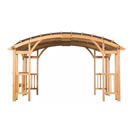
14' x 10'
WOOD PERGOLA
ARTICLE # 254271
ASSEMBLY INSTRUCTIONS
Note: The pergola needs to be installed in cooperation with five people.
The following tools are not included and needed for assembly:
Drill
Tape Measure
Hammer
Screwdriver
Ladder
5 people
If you have comments or questions, please contact BJ's Wholesale Club at 1-800-934-1204.
Carefully check all packaging materials before discarding.
Make sure you have all the parts and hardware as identified on the parts list.
Do not assemble if there are missing pieces.
For any questions, replacement parts or issues about our product,
contact Sunjoy Customer Service at 1-866-578-6569 or email bj@sunjoygroup.com.
Advertisement

Related Manuals for Berkley Jensen 254271


Summary of Contents for Berkley Jensen 254271
- Page 1 14’ x 10’ WOOD PERGOLA ARTICLE # 254271 ASSEMBLY INSTRUCTIONS Note: The pergola needs to be installed in cooperation with five people. The following tools are not included and needed for assembly: Drill Tape Measure Hammer Screwdriver Ladder 5 people If you have comments or questions, please contact BJ’s Wholesale Club at 1-800-934-1204.
-
Page 2: Important Safety Instructions
2 / 30 Important Safety Instructions Warning! To reduce the risk of serious injury, read the following safety instructions before assembling and using the gazebo. Caution! Always keep children under close supervision while they are using or around this product. Never leave children unattended. - Page 3 3 / 30...
-
Page 4: Part List
4 / 30 Part List Description Label Part Number Part Image Big Post 1 P000200183 Big Post 2 P000200184 Screen1 P006300101 Screen2 P006300102 Screen3 P006300103 Small Post 1 P000200416 Small Post 2 P000200417 Small Post 3 P000200418 Small Post 4 P000200419 Small Post 5 P000200426... - Page 5 5 / 30 Cross Beam 4 P000400708 Arc beam 1 P000600561 Arc beam 2 P000600562 Arc beam 3 P000600563 Arc beam 4 P000600564 Connector Panel P000500247 Support Beam 1 P000600565 Support Beam 2 P000600566 Table Top 1 P002100434 Brace (Lower1) P005000346 Table Top2 P002100435...
-
Page 6: Hardware Pack
6 / 30 Hardware Pack Bolt M8*20 H010010164 Bolt M8*30 H010010175 Bolt M8*95 H010010352 Screw M4*20 H030050008 Screw M4*50 H030050060 Screw M4*65 H030050061 Screw M4*95 H030050064 Screw M8*75 H110140002 Flat Washer M8 H050030002 Stake Φ8*180 H070010003 Wrench M8 H090010012... - Page 7 7 / 30 Connect the post base (A) with the screen (03,04,05) ,using the screw (H4).
- Page 8 8 / 30 Connect post Base (A) with the small post (06,07,08), using the screw (H4).
- Page 9 9 / 30 Connect post Base (A) with the Small Post (09,10,11), using the screw (H4 ).
- Page 10 10 / 30 Connect the Cross Beam (13) with the support bar (14). Tighten them using the screw (H7)
- Page 11 11 / 30 Connect the Cross Beam (12) with the assembled frame (step 4) and Small Post (06,09). Tighten them using screw (H6, H7).
- Page 12 12 / 30 Connect the Cross Beam (12) with the assembled frame (step 4) and Small Post (07,08). Tighten them using screw (H6, H7).
- Page 13 13 / 30 Connect the Cross Beam (12) with the assembled frame (step 4) and Small Post (10).Tighten them using screw (H6, H7).
- Page 14 14 / 30 Connect the Cross Beam (12) with the assembled the frame (step 4) and Small Post (11). Tighten them using screw (H6, H7).
- Page 15 15 / 30 Connect the assembled frame (last steps) post with the big post (01,02).Tighten them using screw(H5).
- Page 16 16 / 30 Connect Cross Beam (18) with Cross Beam (19), Small Post (06,07,08,09) and the Big Post (01,02). Tighten them using Bolt (H3) and Flat Washer M8 (H9).
- Page 17 17 / 30 Connect the Arc beam (21) with arc beam (23). Tighten them using the Bolt (H2) and Flat Washer M8 (H9) .
- Page 18 18 / 30 Connect the Connector Panel (24) with Arc beam (21,23),Tighten them using Screw(H5). Connect the Brace (Lower2) (31) with Arc beam(21,23),Tighten them using Screw (H6).
- Page 19 19 / 30 Connect the assembled arc beam with the post. Tighten them using Bolt (H3), Screw (H8), Flat Washer M8 (H9).
- Page 20 20 / 30 Connect arc beam (20) with arc beam (22) ,Tighten them using Bolt (H2) and Flat Washer M8 (H9).Then Connect the Beam Tail(17) with arc beam (20) and arc beam (22) ,Tighten them using screw (H6).
- Page 21 21 / 30 Connectthe Connector Panel(24) with Arc beam(20,22),Tighten them using Screw(H5).Connect the Brace (Lower2) (31)with Arc beam (20,22),Tighten them using Screw (H6).
- Page 22 22 / 30 Connect the assembled arc beam with post. Tighten them using Bolt (H3), Screw (H8) and Flat Washer M8 (H9).
- Page 23 23 / 30 Connect table top (29,30) with cross beam (13).Tighten them using screw (H7).
- Page 24 24 / 30 Connect the brace (lower1) (28) with table top (27).Tighten them using screw (H6).
- Page 25 25 / 30 Connect the assembled table with the post. Tighten them using screw (H5).
- Page 26 26 / 30 Connect short brace (15), long brace (16) with the post, arc beam and beam .Tighten them using screw (H5, H6).
- Page 27 27 / 30 Connect support beam (25,26) with arc beam (20,21,22,23).Tighten them using screw (H7).
- Page 28 28 / 30 Secure canopy (B) to the short side beam .Tighten them using bolt (H1), screw (H8) and flat washer M8 (H9).
- Page 29 29 / 30 Secure the assembled gazebo to the lawn with the stakes (HS).
-
Page 30: Cleaning And Maintenance
30 / 30 Cleaning and Maintenance Caution! Check all screws and nuts periodically for tightness, fastening them again as required. Disassemble the gazebo in the reverse order of the assembly steps. Always disassemble the gazebo completely. A partially disassembled gazebo is not stable enough to resist wind and bad weather, and therefore can be damaged and/or cause damage.
Need help?
Do you have a question about the 254271 and is the answer not in the manual?
Questions and answers