Chapters
Table of Contents

Related Manuals for Comfee SOGNIDORO-09E


Summary of Contents for Comfee SOGNIDORO-09E
- Page 1 Manuale utente e installazione SOGNIDORO-09E SOGNIDORO-12E Nota Importante Leggere con attenzione questo manuale prima di utilizzare il prodotto e conservarlo per la consultazione futura.
-
Page 2: Table Of Contents
Sommario Precauzioni di sicurezza pag. 3-4 Preparazione pag. 5 Installazione pag. 6-10 Funzionamento pag. 11-13 Manutenzione pag. 14 Soluzione Inconvenienti pag. 15 Progettazione e Conformità pag. 15 Smaltimento del prodotto pag. 16 Informazioni sull’assistenza pag. 16-19... -
Page 3: Precauzioni Di Sicurezza
Precauzioni di sicurezza... - Page 4 Precauzioni di sicurezza...
-
Page 5: Preparazione
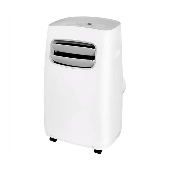
Preparazione Display Filtro aria superiore (contenuto nel telaio in plastica) Maniglie (Sui fianchi del prodotto) Deflettori aria Aspirazione aria superiore Scarico liquido condensa Espulsione aria Filtro aria inferiore Aspirazione aria inferiore Alloggiamento per spina elettrica Passaggio cavo di alimentazione Ruote piroettanti Avvolgicavo Scarico liquido condensa Vista Frontale... -
Page 6: Installazione
Installazione Le immagini contenute nel manuale sono da intendersi come indicative. Il reale aspetto Selezione del luogo di installazione del prodotto, dei componenti e degli accessori, può differire da quanto indicato. Il manuale non comprende informazioni relative al telecomando, contenute in un fascicolo separato. - Page 7 Installazione Assemblaggio del tubo di espulsione aria Attrezzature necessarie Assemblare la tubazione espulsione aria applicando su un lato il raccordo per l’unità e • Cacciavite Philips dimensione media sull’altro il raccordo per l’adattatore finestra o quello per il tappo a parete, in funzione •...
- Page 8 Installazione NOTA Applicare l’estremità del tubo opposta a quella del raccordo dell’adattatore nella macchina, facendo scorrere il raccordo nel senso indicato dalla freccia 3 Segnale la posizione che 1 Afferrare le due parti del 2 Estrarre il kit finestra sino la parte scorrevole kit finestra con le mani.
- Page 9 Installazione FINESTRA CON ANTA SCORREVOLE VERTICALE FINESTRA CON ANTA SCORREVOLE ORIZZONTALE Sigillante Sigillante Kit finestra Kit finestra Kit finestra Sigillante Sigillante 1 Applicare il nastro sigillante 2 Applicare il Kit finestra al serramento ed 2 Applicare il Kit finestra al serramento ed 1 Applicare il nastro al perimetro della finestra.
- Page 10 Installazione FINESTRA CON ANTA SCORREVOLE VERTICALE E ORIZZONTALE DRENAGGIO LIQUIDO CONDENSA 5 Collegare il Durante la modalità Dry e in caso di prodotto con la utilizzo della modalità Cool con tubazione e i elevati valori di umidità ambientale, raccordi a collegare la tubazione di scarico corredo liquido di condensa al bocchettone...
-
Page 11: Funzionamento
Funzionamento Sleep Regolazione della velocità del Avvio/arresto della modalità Power ventilatore: ad ogni pressione Sleep. Accensione/spegnimento la velocità cambia nella Se premuto per 3 secondi dell’unità sequenza Low-Mid-High-Auto consecutivamente, resetta il segnale pulizia filtri. Timer Swing Mode Se premuto a unità spenta attiva Avvio/arresto della Regolazione della temperatura Variazione della modalità... - Page 12 Funzionamento DISPLAY LED ISTRUZIONI PER L’USO FUNZIONAMENTO IN MODALITÀ RAFFREDDAMENTO Premere il pulsante Mode sino a quando il LED della sezione Mode non visualizza la Il display mostra la temperatura impostata per il funzionamento in °C o °F e viene funzione Cool.
- Page 13 Funzionamento Durante l'utilizzo in modalità Auto il sistema deciderà automaticamente se impiegare la La funzione Sleep non è attiva durante l'utilizzo del prodotto in modalità modalità raffreddamento o la modalità ventilazione in funzione della temperatura che è deumidificazione e sola ventilazione. stata selezionata per l'ambiente.
-
Page 14: Manutenzione
Manutenzione PRECAUZIONI DI SICUREZZA Pulire i filtri aria ogni due settimane o a cadenza inferiore, se necessario. • Rimuovere sempre l'alimentazione elettrica prima di ogni operazione di pulizia o • Per la pulizia dei filtri utilizzare una spazzola o un aspirapolvere. È possibile lavare i •... -
Page 15: Soluzione Inconvenienti
Soluzione inconvenienti Progettazione e Conformità Prima di richiedere assistenza sul prodotto, seguite le indicazioni fornite nella tabella MODIFICHE ALLE INFORMAZIONI sotto. Per la nostra politica di continuo aggiornamento dei prodotti, le specifiche e le prestazioni, così come le funzionalità e i dati tecnici, sono soggetti a cambiamenti senza Problematica Possibili cause Soluzioni... -
Page 16: Smaltimento Del Prodotto
Smaltimento del prodotto Informazioni sull’assistenza Questo prodotto contiene fluido refrigerante classificato come infiammabile. Prima svolgere qualunque riparazione su di un prodotto che contiene refrigeranti infiammabili, assicurarsi che siano verificate tutte le misure di sicurezza finalizzate a ridurre il rischio di incendio. Per le riparazioni che coinvolgono il circuito frigorifero le precauzioni elencate in seguito devono essere verificate prima di eseguire qualunque altra operazione. - Page 17 Informazioni sull’assistenza Controlli iniziali sulle componenti elettriche Assicurarsi dell’assenza di fiamme libere o altri inneschi Dove vengono eseguite delle operazioni che coinvolgono il refrigerante o che La riparazione e la manutenzione dei componenti elettrici ed elettronici dovrebbe espongono parti del circuito frigorifero normalmente sigillate, non devono essere includere un controllo iniziale sulla sicurezza dei dispositivi installati.
- Page 18 Informazioni sull’assistenza Saldatura Riparazione dei componenti a sicurezza implicita Qualunque operazione di saldatura eseguita sulle componenti delle unità o Non applicare, in maniera permanente, nessun carico induttivo o capacitivo, tale da sull’impianto, deve essere eseguita soltanto dopo che il refrigerante è stato rimosso dal eccedere le specifiche predefinite in termini di tensione e corrente, ai circuiti del prodotto e dall'impianto.
- Page 19 Non rimuovere le etichette con le indicazioni di sicurezza dal prodotto. In caso di rimozione del prodotto, dopo aver confinato il refrigerante nell'unità esterna, apporre sulla stessa etichetta di indicazione della tipologia e quantità di refrigerante contenuto. Midea Italia S.r.l. Via Lazzaroni 5, 21047 Saronno (VA) -Italia- Tel. 02 96193015 www.comfee.eu...
- Page 21 Portable Air Conditioner (Local Air Conditioner) Instruction Manual SOGNIDORO-09E SOGNIDORO-12E Thank you for purchasing our Portable Air Conditioner. Before using your air conditioner, please read this instruction manual carefully and keep it for future reference. READ AND SAVE THESE INSTRUCTIONS!
- Page 22 Contents P r e p a r a t i o n - - - - - - - - - - - - - - - - - - - - - - - - - - - - - - - - - - - - - - S a f e t y P r e c a u t i o n s - - - - - - - - - - - - - - - - - - - - - - - - - - - - - - C a u t i o n s...
-
Page 23: Preparation
Preparation control panel upper air filter (behind the grille) handle (both sides) horizontal louver upper air intake blade drain outlet Panel air outlet lower air filter lower air intake power plug socket drain outlet (only for pump heating mode) power cord outlet Caster power cord buckle bottom tray... - Page 24 Preparation NOTE: The unit you purchased may be look like one of the following(s):...
-
Page 25: Safety Precautions
Safety Precautions This symbol indicates that ignoring instructions may cause death or serious injury. WARNING: To prevent death or injury to the user or other people and property damage, the following instructions must be followed. Incorrect operation due to ignoring of instructions may cause death, harm or damage. -Installation must be performed according to the installation -DO NOT install your air conditioner in a wet room such as instructions. -
Page 26: Cautions
Cautions Cautions -This appliance can be used by children aged from 8 years and above and person with reduced physical, sensory or mental capabilities or lack of experience and knowledge if they have been given supervision or instruction concerning use of the appliance in a safe way and understand the hazards involved. Children shall not play the appliance. Cleaning and user maintenance shall not be made by children without supervision. -
Page 27: Warning
Warning -Do not use means to accelerate the defrosting process or to clean, other than those recommended by the manufacturer. -The appliance shall be stored in a room without continuously operating ignition sources (for example: open flames, an operating gas appliance or an operating electric heater). -Do not pierce or burn. -
Page 28: Installation
Installation Choosing The Right Location NOTE: All the illustrations in the manual are for explanation purpose only. Your machine may be slightly different. The actual shape shall prevail. The unit can be controlled by the unit control panel alone or with the remote controller. This manual does not include Remote Controller Operations, see the <<Remote Controller Instruction>>... - Page 29 Installation Window Installation Kit(optional) Tools Needed Step One: Preparing the Exhaust Hose assembly -Medium Philips screwdriver; -Tape measure or ruler; -Knife Press the exhaust hose into the window slider adaptor (into wall or scissors; -Saw (optional, to shorten window adaptor for window slider adaptor for wall installation) and unit adaptor, narrow windows) clamp automatically by elastic buckles of the adaptors.
- Page 30 Installation Note: Once the Exhaust Hose assembly and Adjustable Window Slider are prepared, choose from one of the following three installation methods. Type 1: Hung Window Installation(optional) Foam seal B (Adhesive type-shorter) Wi n dow sl i d er A Wi n dow sl i d er B (i f requi r ed) Insert the window slider adaptor Foam seal A...
- Page 31 Installation Type 3: Wall Installation(optional) Foam seal C (Non-adhesive type) -Cut a 125mm (4.9inch) hole into the wall for the Wall Exhaust Adaptor B. Security -Secure the Wall Exhaust Adaptor B to the wall using the four Anchors Bracket and Screws provided in the kit. -Connect the Exhaust Hose Assembly(with Wall Exhaust Adaptor A) to the Wall Exhaust Adaptor B.
-
Page 32: O P E R A T I O
Operation Wireless Wireless button(optional) function and the LED DISPLAY shows 'OF' for 3 Used to initiate the wireless connection mode. For seconds, press Wireless button to turn on Wireless Wireless the first time to use wireless function, press the function and the LED DISPLAY shows 'ON' for 3 seconds. - Page 33 Operation Mode button Sleep(Eco)/Filter button Selects the appropriate operating mode. Each time Used to initiate the SLEEP/ECO operation. you press the button, a mode is selected in a NOTE: After 250 hours of operation, the filter sequence that goes from AUTO, COOL, DRY, FAN indicator light illuminates.
- Page 34 Operation LED display Operation Instructions Shows the set temperature in °C or °F and the COOL operation Auto-timer settings. While on DRY and FAN modes, -Press the "MODE" button until the "COOL" indicator light it shows the room temperature. comes on. Shows Error codes and protection code: -Press the ADJUST buttons "+"...
- Page 35 Operation -Keep windows and doors closed for the best illuminates. Press the UP or DOWN button to select the dehumidifying effect. desired time. Press the TIMER button again within 5 -Do not put the duct to window. seconds, the Auto-on start program is initiated. And the TIMER ON indicator light illuminates.
- Page 36 Operation minutes.The temperature will then increase (cooling) or AUTO-RESTART(on some models) decrease (heating) by another 1°C/2°F(or 1°F) after an If the unit breaks off unexpectedly due to the power cut,it will restart with the previous function setting automatically additional 30 minutes. This new temperature will be when the power resumes.
- Page 37 Operation Water drainage Direct the hose toward the drain, making sure that there are no kinks that -During dehumidifying modes, will stop the warter flowing.Place the end of the hose into he drain and remove the upper drain plug Remove the make sure the end of the hose is down to let the water flow smoothly.
-
Page 38: M A I N T E N A N C
Maintenance Maintenance Tips WARNING: -Be sure to clean the air filter every 2 weeks for optimal -Always unplug the unit before cleaning or servicing. performance. -DO NOT use flammable liquids or chemicals to clean the -The water collection tray should be drained immediately unit. - Page 39 Faults Diagnosis Please check the machine according to the following form before asking for maintenance: Problem Possible Cause Troubleshooting Unit does not The Water Collection Tray is full. Turn off the unit, drain P1 Error Code turn on when the water from the Water Collection Tray and restart the unit. pressing ON/OFF In COOL mode: room temperature is lower than Reset the temperature...
- Page 40 Design and Compliance Notes Design Notice Note:The model MPPFB-11CRN7-QB6 should be connected only to a supply with the relevant system In order to ensure the optimal performance of our products, impedance no more than 0.373 ohm. Restrictions to the design specifications of the unit and remote control are connection may be imposed by the supply authority subject to change without prior notice.
- Page 41 Sociable Remark When using this dehumidifier in the European countries, the following information must be followed: DISPOSAL: Do not dispose this product as unsorted municipal waste. Collection of such waste separately for special treatment is necessary. It is prohibited to dispose of this appliance in domestic household waste. For disposal, there are several possibilities: A) The municipality has established collection systems, where electronic waste can be disposed of at least free of charge to the user.
- Page 42 Other tips 1.Transport of equipment containing flammable refrigerants 3)General work area See transport regulations All maintenance staff and others working in the local area 2.Marking of equipment using signs shall be instructed on the nature of work being carried out. See local regulations Work in confined spaces shall be avoided.
- Page 43 Other tips explosion. All possible ignition sources, including cigarette adequately and are not obstructed; smoking, should be kept sufficiently far away from the site If an indirect refrigerating circuit is being used, the of installation, repairing, removing and disposal, during secondary circuit shall be checked for the presence of which flammable refrigerant can possibly be released to the refrigerant;...
- Page 44 Other tips exposed while charging, recovering or purging the system; Do not apply any permanent inductive or capacitance That there is continuity of earth bonding. loads to the circuit without ensuring that this will not 7.Repairs to sealed components exceed the permissible voltage and current permitted for 1)During repairs to sealed components, all electrical the equipment in use.
- Page 45 Other tips may need re-calibration. (Detection equipment shall be Evacuate; calibrated in a refrigerant-free area.) Ensure that the Purge again with inert gas; detector is not a potential source of ignition and is suitable Open the circuit by cutting or brazing. for the refrigerant used.
- Page 46 Other tips Extreme care shall be taken not to overfill the refrigeration refrigerant can be removed from various parts of the system. Prior to recharging the system it shall be pressure system. tested with OFN. The system shall be leak tested on f) Make sure that cylinder is situated on the scales before completion of charging but prior to commissioning.
- Page 47 Other tips practice that all refrigerants are removed safely. or compressor oils are to be removed, ensure that they When transferring refrigerant into cylinders, ensure that only have been evacuated to an acceptable level to make appropriate refrigerant recovery cylinders are employed. certain that flammable refrigerant does not remain within Ensure that the correct number of cylinders for holding the the lubricant.
- Page 49 Mobiles Klimagerät (Lokale Klimaanlage) Bedienungsanleitung SOGNIDORO-09E SOGNIDORO-12E Danke, dass Sie sich für unser mobiles Klimagerät entschieden haben. Bevor Sie Ihr Klimagerät verwenden, lesen Sie bitte diese Bedienungsanleitung sorgfältig durch und heben Sie diese für das Nachschlagen auf. LESEN UND VERWAHREN SIE DIESE ANLEITUNG!
- Page 50 | Inhalt Allgemeine Beschreibung ---------------------------------------------------------- 2 Sicherheitshinweise ----------------------------------------------------------------- 4 Sicherheitswarnungen -------------------------------------------------------------- 5 Sicherheitswarnungen; Mindestraumgröße- Warnungen ------------------ 6 Installation ----------------------------------------------------------------------------- 7 Betrieb ---------------------------------------------------------------------------------- 11 Wartung -------------------------------------------------------------------------------- 16 Fehlerdiagnose ----------------------------------------------------------------------- 17 Hinweise zu Konstruktion und Konformität ------------------------------------ 18 Herstellerhinweis --------------------------------------------------------------------- 19 Weitere Tipps ------------------------------------------------------------------------- 20...
-
Page 51: Allgemeine Beschreibung
I Allgemeine Beschreibung Bedienfeld Oberer Luftfilter (hinter dem Gitter) Griff oberer Lufteinlass Horizontale Ausblaslamelle Abflussöffnung Luftauslass Paneel Unterer Luftfilter Unterer Lufteinlass Gerätestecker Kondensatablauf (nur für Wärmepumpenmodus) Netzkabelausgang Netzkabelhalterung Ablauf Kondensatbehälter Vorderseite Rollen Rückseite... - Page 52 I Allgemeine Beschreibung HINWEIS: Das von Ihnen gekaufte Gerät entspricht (einer) der folgenden Darstellung(en):...
-
Page 53: Sicherheitshinweise
I Sicherheitshinweise - Ändern Sie NICHT die Länge des Netzkabels und verwenden Sie KEIN Verlängerungskabel. Verwenden Sie eine Einzelsteck- B e lesen Sie diese Hinweise sorgfäl g durch, bevor Sie dose nicht zugleich für andere elektrische Geräte. Unsachge- mit der Installa on beginnen. Falsche Bedienung oder mäße oder unzureichende Stromversorgung kann zu Feuer o- eine unsachgemäße Installa on können Schäden an Ih- der elektrischen Schlägen führen. - Page 54 - Wenn sich in der Umgebung des Geräts brennbare Gase ansam- - Dieses Gerät kann von Kindern ab 8 Jahren und von Personen mit meln, kann dies zu einer Explosion und Feuer führen. eingeschränkten physischen, sensorischen oder geistigen Fähig- - Verlegen Sie das Anschlusskabel nicht unter Teppichen. Decken keiten oder mangelnder Erfahrung betrieben werden, wenn eine Sie das Kabel nicht mit Teppichläufern o.ä.
-
Page 55: Sicherheitswarnungen; Mindestraumgröße- Warnungen
I Sicherheitswarnungen; Mindestraumgröße Warnung - Verwenden Sie nur die vom Hersteller empfohlenen Mittel für - Sorgen Sie dafür, dass das Gerät in einem gut belüfteten Raum aufbewahrt wird, der mindestens so groß ist, wie er für den Be- das Abtauen. - Das Gerät sollte nicht in einem Raum gelagert werden, in denen trieb empfohlen ist. -
Page 56: Installation
I Installation HINWEIS: Alle Abbildungen in dieser Bedienungsanleitung dienen le- Wahl des richtigen Aufstellorts diglich zur Illustration. Ihr Gerät kann davon leicht abwei- chen. Die tatsächliche Form ist maßgebend. Das Gerät kann über das Bedienfeld oder mit der Fernbedienung ge- steuert werden. - Page 57 Fensterset I Installation Schritt eins: Vorbereiten des Abluftschlauchs: Benötigte Werkzeuge Drücken Sie den Abluftschlauch in den Schiebefensteradapter - Mittlerer Schraubendreher Philips PH2; - Maßband oder Li- (bei Wandmontage den Wandauslassadapter A) und auf der an- deren Seite das Adapterstück für das Gerät, sie fixieren sich auto- neal;...
- Page 58 I Installation Hinweis: Sind die Abluftschlauchbaugruppe und der verstell- bare Fensterschieber vorbereitet, wählen Sie eine der drei folgenden Montagemethoden. Typ 1: Vertikales Schiebefenster Setzen Sie den Schiebefensteradapter in Schaumdichtung B (kürzere, selbstklebende Dichtung) die Öffnung des Fensterschiebers ein. Fensterschieber B (wenn erforderlich) Fensterschieber A Typ 2: Horizontales Schiebefenster...
- Page 59 Typ 3: Wandmontage I Installation Schneiden Sie ein Loch mit 125 mm (4.9 inch) Durchmesser Schaumdichtung C in die Wand für Wandauslassadapter B. (Nicht selbstklebend) Befestigen Sie den Wandauslassadapter B mit den Schrau- Sicherheits- klammer ben und Dübeln aus dem Set. ...
-
Page 60: Betrieb
| Betrieb *optional *optional (3s Filter zurücksetzen) (3s Ion aktivieren Swing-Taste (optional) Timer-Taste Modus-Taste Wählt den gewünschten Betriebsmodus. Jedes Wird dazu verwendet, die AUTO EIN-Startzeit und Zum Einschalten der Auto- Mal wenn Sie die Taste drücken, wird ein Modus in die AUTO AUS-Stoppzeit einzustellen, in Verbin- Schwenk-Funktion. - Page 62 Drücken Sie die TIMER-Taste noch einmal innerhalb von 5 Sekun- | Betrieb den, und das AUTO AUS Programm wird aktiviert. Das Klimagerät regelt die Raumtemperatur automatisch um Drücken Sie oder halten Sie die + oder – Taste gedrückt, um die den Vorgabewert der Temperatur, den Sie eingestellt haben.
- Page 63 ANPASSEN DES LUFTSTROMS: | Betrieb Die Ausblaslamelle kann automatisch oszillierend betrieben wer- Weitere Merkmale den. Die Luftrichtung einstellen: Funktionen FOLLOW ME / TEMPERATURFÜHLER (optio- Wenn das Gerät eingeschaltet wird, öffnet die Ausblaslamelle nal) NOTE: Diese Funktion kann NUR von der Fernbedie- vollständig.
- Page 64 Ende des Schlauchs direkt über einem Abfluss Ihres Fußbodens. HINWEIS: Stellen Sie sicher, dass der Schlauch fest und dicht sitzt. | Betrieb Den Schlauch in ein Waschbecken leiten: Führen Sie den Schlauch Wasserablauf: ohne Knicke etc. zum Waschbecken, damit sich das Wasser nicht ...
-
Page 66: Fehlerdiagnose
I Fehlerdiagnose Überprüfen Sie das Gerät nach den folgenden Empfehlungen, bevor Sie den Wartungsdienst rufen: Problem Mögliche Ursache Fehlerbehebung Der Kondensatauffangbehälter ist voll. Schalten Sie das Gerät aus, Das Gerät schaltet P1 Fehlercode leeren Sie den Kondensatauffangbehälter und starten Sie das Ge- sich nicht ein, wenn rät wieder. -
Page 67: Hinweise Zu Konstruktion Und Konformität
| Hinweise zu Konstruktion und Konformität Konstruktionshinweis Hinweis: Achten auf eine ausreichende Absicherung und Um die optimale Leistung unserer Produkte zu gewährleisten, ausreichende Kabelquerschnitte. können die Konstruktion und technischen Spezifikationen des Geräts und der Fernbedienung ohne vorherige Ankündi- gung geändert werden. Installation des Abluftschlauchs: Energiebewertung Entsprechend zur Nutzungsart müssen Abluftschlauch und... -
Page 68: Herstellerhinweis
| Herstellerhinweis Wenn Sie diesen Luftentfeuchter in europäischen Ländern verwenden, beachten Sie bitte die folgenden Informationen: ENTSORGUNG: Entsorgen Sie dieses Produkt nicht über den unsortierten Hausmüll. Für die kontrollierte Aufbereitung von Ab- fall dieser Art ist eine getrennte Sammlung erforderlich. Die Entsorgung des Geräts über den Hausmüll ist verboten. -
Page 69: Weitere Tipps
| Weitere Tipps 3) Arbeitsbereich: 1. Transport von Geräten, die brennbare Kältemittel enthalten: Beachten Das gesamte Wartungspersonal und anderen Personen, die im lokalen Sie die Transportvorschriften. Arbeitsbereich arbeiten, müssen in die Art der durchzuführenden Arbeit 2. Kennzeichnung von Geräten: Beachten Sie unterwiesen werden. - Page 70 | Weitere Tipps und die Ein- und Auslässe nicht verlegt sind. Wird ein indirekter Käl- tekreislauf verwendet, so ist der Sekundärkreislauf auf das Vorhan- Alle möglichen Zündquellen, einschließlich Rauchen, müssen sich aus- densein von Kältemittel zu prüfen. Die Kennzeichnung der Ausrüs- reichend weit entfernt vom Arbeitsbereich für die Reparatur oder Ent- tung muss sichtbar und lesbar sein.
- Page 71 Weitere Tipps: Legen Sie keine dauerhaften induktiven oder kapazitiven Lasten im Stromkreis an, ohne sicherzustellen, dass dies die zulässige Spannung während der Reparatur, beim Befüllen und Entlüften des Systems span- und den zulässigen Strom für das verwendete Gerät nicht übersteigt. nungsfrei sein.
- Page 72 | Weitere Tipps Entlüften; eine erneute Kalibrierung erforderlich ist. (Die Kalibrierung muss in ei- Neuerlich mit Inertgas spülen; nem Bereich erfolgen, der frei von Kältemitteln ist). Stellen Sie sicher, Den Kreislauf durch Schneiden oder Löten öffnen. dass das Lecksuchgerät keine potentielle Zündquelle ist und für das Die Kältemittelfüllung muss in dafür geeignete Kältemittelbehälter abge- verwendete Kältemittel geeignet ist.
- Page 73 | Weitere Tipps damit das Kältemittel aus verschiedenen Teilen des Systems ent- fernt werden kann. Es ist besonders darauf zu achten, dass der Kältekreislauf nicht über- f) Stellen Sie sicher, dass der Behälter auf der Waage steht, bevor füllt wird. Vor dem Befüllen des Systems muss es mit OFN druckge- die Rückgewinnung beginnt.
- Page 74 | Weitere Tipps schen Komponenten entsprechend versiegelt sind, um eine Zündung im muss das gesamte Kältemittel fachgerecht entfernt werden. Verwenden Falle einer Kältemittelfreisetzung zu verhindern. Konsultieren Sie im Sie nur geeignete Kältemittelbehälter für das Ablassen. Zweifelsfall den Hersteller. Stellen Sie die ausreichende Anzahl von Behältern bereit. Alle Behälter Das rückgewonnene Kältemittel ist dem Kältemittellieferanten im richti- müssen die Anforderungen erfüllen (d.h.
- Page 75 MOBILE TYPE AIR CONDITIONERS MOBILE TYPE AIR CONDITIONERS ( LOCAL AIR CONDITIONERS ) ( LOCAL AIR CONDITIONERS ) SOGNIDORO-09E MODEL MODEL SOGNIDORO-12E COOLING CAPACITY 9000Btu/h COOLING CAPACITY 12000Btu/h HEATING CAPACITY HEATING CAPACITY MAXIMUM ALLOWABLE DISCHARGE 2.6MPa 2.6 MPa EXCESSIVE OPERATING...
Need help?
Do you have a question about the SOGNIDORO-09E and is the answer not in the manual?
Questions and answers