Table of Contents
Advertisement
Quick Links
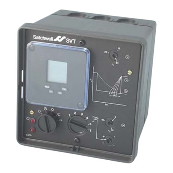
Satchwell
7-DAY OPTIMISER
The SVT is a fuel-saving controller which can replace a conventional
time switch on a heating system and provides a variable start time
dependent on the fall of room temperature during the off period.
It is used to switch on and off central heating systems and will
substantially reduce fuel consumption compared with fixed time
starting. In all but the very coldest weather the start time is delayed until
the latest time consistent with the amount of heat necessary to regain
the required temperature at occupancy time. In very mild weather this
delay can be as much as five hours later than in cold weather and fuel
savings of between 10% and 25% are possible.
By relating the start time to the inside temperature rather than the
outside temperature, the insulation and thermal mass of the building
are taken into account.
The SVT makes the benefits of optimum start control available for
small buildings because the capital outlay for the installation is low and
no skilled personnel are needed to operate it.
FEATURES
• Easy installation - only one sensor required (packed with the
controller)
• Programme override switch
• Choice of day control by separate compensator or built-in
on/off day control
• Minimum night 'inside' temperature
• Analogue and Digital clock versions available
Data Sheets
Controllers
DS 2.021 - CSC
Multi-Lingual Instructions
MLI 2.001 - Mounting Details
TM
SVT
Satchwell
Advertisement
Table of Contents

Subscribe to Our Youtube Channel
Related Manuals for t.a.c. Satchwell SVT


Summary of Contents for t.a.c. Satchwell SVT
- Page 1 Satchwell 7-DAY OPTIMISER The SVT is a fuel-saving controller which can replace a conventional time switch on a heating system and provides a variable start time dependent on the fall of room temperature during the off period. It is used to switch on and off central heating systems and will substantially reduce fuel consumption compared with fixed time starting.
-
Page 2: Specification
SPECIFICATION Type: Fuse: SVT 4201 - Analogue Clock - Specification no. 588-4-201 Analogue - Transformer secondary: 250mA SVT 4251 - Digital Clock - Specification no. 588-4-251 Digital - Transformer secondary: 315mA (20mm) Spare fuse provided. Associated Sensor: STR614 (included with controller). Power Failure Reserve: Digital - Capacitor - For clock (when fully charged): - 100 hours. -
Page 3: Installation
INSTALLATION WALL MOUNTING Fig.7 Fig.5 Fig.4 Fig.8 Fig.6 FLUSH PANEL MOUNTING Fig.12 Fig.15 Fig.9 Fig.11 Fig.10 Fig.13 Fig.14 1. Select location which is reasonably clean and dry, with adequate c. Ensure all necessary links and resistors have been connected access. Ambient limits 0 to 40°C. or removed as instructed. -
Page 4: Setting The Digital Clock
SETTING THE CONTROLLER (SEE FIG.1). Cautions DO NOT rotate the outer dial in any direction. 1. Set Td to required 'Day' temperature during occupancy. DO NOT rotate the minute hand anti-clockwise as this will damage 2. Set Tn to minimum 'Night' temperature during unoccupied periods. the mechanism. - Page 5 2. SETTING SUMMER/WINTER TIME SU mmer WI nter SU WI TIME/DATE SU WI TIME/DATE SU WI TIME/DATE SU WI SU WI SU WI PROG MODE SU WI MONTH MONTH YEAR YEAR TIME/DATE SU WI MONTH MONTH YEAR 3. SETTING THE PROGRAM Programming One program = switch-on time + switch-off time + switch-on and switch-off days Programs with predefined switch-on / switch-off days...
- Page 6 3. SETTING THE PROGRAM (CONTINUED) PROG MODIFY TEST PROG PROG PROG PROG PROG PROG • • • 1 - 7 1 - 5 PROG PROG 6 - 7 Select switch-on day Tuesday Select switch-off day Tuesday PROG PROG...
- Page 7 4. MODIFYING THE PROGRAM TIME/DATE SU WI PROG PROG MODIFY TEST PROG MODIFY PROG PROG MODIFY TEST MODIFY TEST MODE MODE Edit program PROG MODIFY PROG Prog 2 MODIFY Prog 1 Prog 3 PROG MODIFY PROG PROG MODIFY MODIFY • • • PROG MODIFY PROG...
-
Page 8: Wiring Precautions
5. TESTING THE PROGRAM prog -> Programs in the order entered SERIAL -> Switching commands in chronological order DAY 1 DAY 2 PROG PROG PROG MODIFY TEST PROG TEST TEST PROG TEST TEST PROG TEST • • • • • • Prog 1 Prog 2 PROG... -
Page 9: Connection Diagrams
CONNECTION DIAGRAMS BASIC CONNECTIONS REMOTE HOLIDAY SWITCH RECORDER OUTPUT FOR TEMPERATURE INDICATION The switch takes effect at RECORDER RECORDER 0 the next switch on time 0 to 10Vdc to 100mV input 1 & 2 - PLANT (Boiler/Pump) HOLIDAY (Open) 3 - DAY AUTO (Closed) 4 - BOOST 5 - COMMON... - Page 10 WARNINGS - ELECTRICAL SHOCK HAZARD. REMOVE ALL POWER FROM BOTH THE CONTROLLER AND RELAY OUTPUTS BEFORE MAKING TERMINATIONS. ALL RELAY OUTPUTS MUST USE A COMMON VOLTAGE I.E. 230Vac OR 24Vac. DO NOT MIX VOLTAGES. THIS IS REQUIRED TO PREVENT THE POSSIBILITY OF FLASHOVER FROM 230Vac TO 24Vac.
Need help?
Do you have a question about the Satchwell SVT and is the answer not in the manual?
Questions and answers