Advertisement
Quick Links
Forta M1500A series Non-Spring Return linear actuators are
designed to mount directly on to VB-72xx two way globe
valve with a AV-811 linkage kit (ordered separately) or VB-
8xxx two and three way globe valves and VB-9313-0-5-xx
three way globe valves with a AV-812 valve linkage kit (ordered
separately).
Applications include chilled or hot water and steam.
Field selectable input signals include reverse and direct
acting, Floating or Proportional 0-10, 2-10 vdc or 4-20 ma with
500 Ohm resistor (supplied) plus proportional sequencing
input signal ranges.
FEATURES
- Floating configuration controlled by a SPDT floating
controllers
- Proportional configuration 0-10, 2-10 vdc or 4-20 ma with
the addition of a 500 ohm resistor included
Direct/Reverse action switch selectable
- 337lbf (1500N) linear force
- 24 Vac powered
- Die-cast housing with plenum rated plastic cover for NEMA
2 (IP54) applications
- Manual override to allow positioning of valve
- Electronic valve sequencing and Electronic flow curve
(equal percentage or Linear) selection.
- Torque overload protection throughout stroke
- Easy "One Touch" input signal/stroke calibration
APPLICABLE LITERATURE
- Forta/VB-7xxx Selection Guide, F-27490
- Forta/VB-8xxx, VB-9xxx Selection Guide, F-27491
- AV-811 Linkage VB-7xxx, F-27442
- AV-812 Linkage VB-8xxx, VB-9xxx, F-27443
- AV-800 Series Linkage Adapters for Competitors Valves,
F-27470
TECHNICAL DATA, M1500A
Model Chart
Model
Power
Running VA
M1500A
24vac ±10%
50-60Hz
M1500A-S2
* 4-20mA with 500 ohm resistor
Stroke
>3/8" to 2" (9-52mm)
Stroke Timing
Floating 60 or 300 sec selectable
Proportional 15 sec @1/2" stroke
Feedback AO
2-10 vdc
Power Supply Type
Half Wave
Motor Type
Brushless DC
Enclosure
NEMA 2 (IP 54) with both conduit
connectors used. NEMA 1 IP40 with
one connector used.
Sound Power Level
max 32 dba
Agency Listings
UL873, cULus, C-tick, CE
Subject to modification.
TAC Forta M1500A
Globe Valve Actuator General instructions
Transformer
Floating
Size VA
Control
24
50
Yes
1 (10)
Proportional Control
Feedback
0-10vdc, 2-10vdc or
2-10vdc
4-20mA*
Ambient Temperature
Storage
-13 °F-+149 °F (-25- +65 °C) ambient
Operational
122 °F (50 °C) For Chilled water
applications
113 °F (45°C) ambient at 281 °F
(138°C) Fluid temperature
107 °F (42 °C) ambient at 300 °F
(149 °C) Fluid temperature
100 °F (38 °C) ambient at 340 °F
(171°C) Fluid temperature
90°F (32°C) ambient at 366 °F
(186 °C) Fluid temperature
Min. Operating Temp.
14 °F (-10 °C)
Ambient Humidity
15 to 95 % RH non condensing
Materials
Housing
Die-Cast Aluminum
Cover
UL94 plenum rated plastic
Weight
3.96 lb (1.8kg)
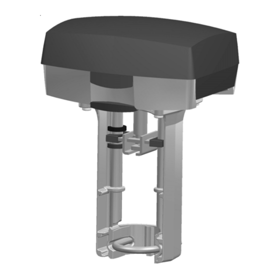
Dimensions
Figure 1
DIM121E
12 Mar 2008
2-SPDT Aux
Force lbf
Switch
No
337 (1500 N)
24vac 4a res
F-27507-1
DIM121E
Advertisement

Related Manuals for t.a.c. Forta M1500A


Summary of Contents for t.a.c. Forta M1500A
- Page 1 TAC Forta M1500A 12 Mar 2008 Globe Valve Actuator General instructions Forta M1500A series Non-Spring Return linear actuators are designed to mount directly on to VB-72xx two way globe valve with a AV-811 linkage kit (ordered separately) or VB- 8xxx two and three way globe valves and VB-9313-0-5-xx three way globe valves with a AV-812 valve linkage kit (ordered separately).
- Page 2 3. Forta M1500A series linear actuators are designed to mount directly on to VB- 72xx two way globe valves with a AV-811 linkage kit valve...
- Page 3 CONNECTIONS Cable Lengths: The wires to G, H Block Function Description Caution: For floating input signals the should be max of 328 ft (100m). min cables between the controller and the 24 vac power AWG 16, all other proportional input Forta should not exceed 328' (100m) 24 vac power...
-
Page 4: Wiring Examples
WIRING EXAMPLES Figure 6 DIM121E F-27507-1 4 (10) - Page 5 Figure 7 5 (10) F-27507-1 DIM121E...
- Page 6 PROGRAM SWITCH SETTINGS Function in the Description “OFF” pos. “ON” position 1 Retract Extend (see sw7) Valve closing screw direction 2 Proportional Floating Control Mode 3 – Sequence Sequence control 4 0-10 V 2-10 V Input Voltage range 5 0-5 V, 2-6 V 5-10 V, 6-10 V Part of voltage range 6 60 s...
- Page 7 VB-72xx and 82xx or 92xx Two Way Globe Valve, Forta Proportional Control Setup Reference Table 1 VB-x2xx 2 way valves Forta M1500A Base Proportional Configuration Valve Type Program Switch Position Desired Valve Operations Low end Valve position Input of signal...
- Page 8 EXTEND/RETEACT MOVEMENT OF THE ACTUATOR. VB-72xx and 82xx or 92xx Two Way Globe Valve, Forta Floating Control Setup Reference Table 4 VB-x2xx 2 way valves Forta M1500A Base Floating Configuration Valve Type Program Switch Position Input / Output Valve position...
- Page 9 VB-8303 and VB-9313 Three Way Globe Valve, Forta Floating Control Setup Reference Table 5 VB-8303 3 way valves Diverting / Mixing Forta M1500A Base Floating Configuration Valve Type Program Switch Position Desired Valve Operations Valve position with Power up Power to D2...
-
Page 10: Actuator Installation
ACTUATOR INSTALLATION Refer to AV-811 or AV-812 for complete mounting instructions Mount actuator as shown and firmly tighten the U-clamp with a 13 mm wrench. Remove cover and discard the shipping bubble wrap. Forta closes the valve and opens it When the end position adjustment is The switches on the circuit board fully.
Need help?
Do you have a question about the Forta M1500A and is the answer not in the manual?
Questions and answers