Table of Contents
Advertisement
Quick Links
Application
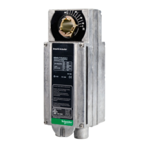
TAC DuraDrive Direct Coupled Actuators are designed
to be used in both damper and valve control
applications. The follow general instructions are for
damper applications, refer to the Applicable Literature
table for valve literature.
The MA40-717X series actuators are over the shaft
spring return actuators used for two-position control
applications.
Features
•
150 lb-in (17 N-m) rated torque
•
NEMA Type 4 housing (IEC IP56)
•
Custom automatic current sensing motor control
provides extended reliability and repeatable timing
•
Direct coupled to the damper shaft with dual
industrial hardened universal mounting clamps
•
Two-position actuator controlled by SPST controller
•
Clockwise or counterclockwise spring return is
determined by actuator mounting position
•
Accurate 93° travel digitally controlled
•
Integral position indication scale
•
Rugged die-cast housing
•
Oil immersed gear train provides continuous
lubrication
•
Rated for operating temperature up to 140 °F
•
Five year warranty
Printed in U.S.A. 8-06
TAC
1354 Clifford Avenue
P. O. Box 2940
Loves Park, IL 61132-2940
www.tac.com
© Copyright 2006 TAC All Rights Reserved.
MA40-717X Series
TAC DuraDrive™ Series Spring Return
Two Position Actuators
General Instructions
†
† Refer to Table-1 to identify specific models that are
in conformance with CE standards.
F-26742-2
Advertisement
Table of Contents

Subscribe to Our Youtube Channel
Related Manuals for t.a.c. DuraDrive MA40-717 Series


Summary of Contents for t.a.c. DuraDrive MA40-717 Series
- Page 1 MA40-717X Series 1354 Clifford Avenue P. O. Box 2940 Loves Park, IL 61132-2940 TAC DuraDrive™ Series Spring Return www.tac.com Two Position Actuators General Instructions Application TAC DuraDrive Direct Coupled Actuators are designed to be used in both damper and valve control applications.
-
Page 2: Applicable Literature
Applicable Literature F-Number Description Audience Purpose – Sales Personnel Describes the globe valve actuator/linkage – Application Engineers MX40-6XXX-2XX, MX40-7XXX-2XX Series assembly’s features, specifications, and F-26750 – Installers Actuator/Linkage Assemblies General Instructions possible applications. Provides step-by- – Service Personnel step mounting instructions. –... -
Page 3: Specifications
SPECIFICATIONS Inputs Control Signal: Two wire, SPST or Triacs. See Figure-1 through Figure-1. Power Input: See Table-1. All 24 Vac circuits are Class 2. All circuits 30 Vac and above are Class 1. Connections: Power, 24 inch (61 cm) long, 18 AWG color coded pigtail leads. Control, 24 inch (61 cm) long, 22 AWG color coded pigtail leads. -
Page 4: Typical Applications (Wiring Diagrams)
Table-1 Model Chart. Actuator Power Input Approximate 93° Rotation Output Torque Rating Part Timing in Seconds lb.-in. (N-m) Number @ 70° F (21° C) Voltage Watts Running Holding Minimum Maximum Stall for Rated Torque MA40-7173 24 Vac ±20% MA40-7170 120 Vac ±10% 50 60 11.4 150 (17) -
Page 5: Installation
MA40-7173 Black 24 Vac Black/Blue Green/Yellow 1 SPST or Triac Controller. Multiple MA40-7173 actuators may be powered by a single 24 Vac transofrmer. 2 Unused conduit port must remain plugged with a water tight pipe plug as shipped from factory to maintain NEMA Type 4 or IP56 rating. 3 Ground wire may be Green on some models. - Page 6 Precautions General Warning: • Electrical shock hazard! Disconnect the power supply (line power) before and during installation to prevent electric shock and equipment damage. • Make all connections in accordance with the wiring diagram and in accordance with national and local electrical codes. Use copper conductors only. Caution: •...
- Page 7 Mounting Mount the TAC DuraDrive Actuator directly on the damper shaft in locations that clear the maximum dimensions of the actuator case and allow the actuator to be mounted flush to the surface of the terminal box and perpendicular to the damper shaft. Note: Some terminal boxes have sheet metal screw heads or other protrusions near the damper shaft.
- Page 8 Mounting the Actuator for Clockwise or Counterclockwise Spring Return The zero (0) position on the position indicator is the normal or spring return position. When the actuator is mounted with the “R” side facing the installer and the control signal increases the actuator will rotate in the counterclockwise direction.
- Page 9 CENTERLINE 1 Two AM-754 Universal Mounting Clamp Assemblies are provided with each actuator. Each clamp assembly includes 1 universal mounting clamp and 1 retaining clip. Two Universal Mounting Clamp Assemblies are required for all mounting configurations. Figure-5 Long Damper Shaft Mounting with Clockwise Spring Return for Normally Closed Damper. ©...
- Page 10 CENTERLINE 1 Two AM-754 Universal Mounting Clamp Assemblies are provided with each actuator. Each clamp assembly includes 1 universal mounting clamp and 1 retaining clip. Two Universal Mounting Clamp Assemblies are required for all mounting configurations. Figure-6 Long Damper Shaft Mounting with Counterclockwise Spring Return for Normally Closed Damper. Actuator Mounting Slot AM-751 Anti-rotation Bracket...
- Page 11 Short Damper Shaft See Figure-8 for installation of actuator using the AM-676 Universal Shaft Extension. Installation requires AM-676 Universal Shaft Extension and AM-753 Universal Mounting Clamps for 3/4" to 1" (19 to 25 mm) shafts, these items must be ordered separately. 1.
-
Page 12: Wiring Requirements
Actuator AM-753 Anti-rotation Bracket Universal (included with Mounting Clamp Assemblies actuator) AM-676 Universal Shaft Mounting Surface Extension V-clamp Duct 1 The AM-676 extends the damper shaft approximately 9" (229 mm). Damper Shaft Figure-8 Installation of Universal Shaft Extension. Wiring Requirements Control and Power Leads Remove blue plastic thread protectors before installing conduit fittings. -
Page 13: Theory Of Operation
CHECKOUT This procedure is for checking out a normally closed actuator that is typically mounted unpowered. It is possible to mount the actuator with power applied for special applications. Note: To check out a normally open actuator the procedure is the same as below, except the initial position is open and the powered position is closed. -
Page 14: Dimensional Data
DIMENSIONAL DATA Figure-9 dimensions are in inches (mm). 4" (102) 4" (102) 1-27/64" (36) 10-27/32" (275) Figure-9 MA40-717X Damper Actuator. © Copyright 2006 TAC All Rights Reserved. F-26742-2... - Page 15 © Copyright 2006 TAC All Rights Reserved. F-26742-2...
- Page 16 Copyright 2006, TAC All brand names, trademarks and registered 1354 Clifford Avenue trademarks are the property of their respective P.O. Box 2940 owners. Information contained within this Loves Park, IL 61132-2940 document is subject to change without notice. F-26742-2 www.tac.com...
Need help?
Do you have a question about the DuraDrive MA40-717 Series and is the answer not in the manual?
Questions and answers