Table of Contents
Advertisement
Quick Links
Advertisement
Table of Contents

Related Manuals for VOLTCRAFT GT-6000


Summary of Contents for VOLTCRAFT GT-6000
- Page 1 Operating Instructions Device tester GT-6000 v2 Item No. 2362387 Page 2 - 34...
-
Page 2: Table Of Contents
Table of contents Page Introduction ................................3 Explanation of symbols ............................3 Intended use ................................4 Delivery contents ..............................5 Optional accessories ............................5 Transport and storage ............................6 Safety instructions ...............................6 Operation elements and connections ........................8 Carrying out Measurements ..........................13 a) Testing a mains power outlet ........................13 b) Testing devices of protection class 1 ......................14 c) Testing devices of protection class 2 (insulated) and devices of protection class 3 (safety low voltage) ...17 d) Lead test - testing of power / extensions cables, cable reels and multi-plugs ..........19... -
Page 3: Introduction
1. Introduction Dear customer, Thank you for purchasing this product. This product complies with the statutory national and European requirements. To maintain this status and to ensure safe operation, you as the user must observe these operating instructions! These operating instructions are part of this product. They contain important notes on commissioning and handling. -
Page 4: Intended Use
Tester GT-6000 v2 is characterized by the following features: • Test results of GT-6000 v2 are compared with preset values of limits and based on that pass/fail information is given to user. Preset values of limits and more information regarding test can be found in last versions of standards. -
Page 5: Delivery Contents
4. Delivery contents • Device tester GT-6000 v2 • 1 mains cable (IEC 60320 C19) • 1 test lead with alligator clip • 1 IEC power cable (IEC adapter cable IEC 60320 C13) • 1 USB-C connection cable (USB-A connector to USB-C socket) •... -
Page 6: Transport And Storage
6. Transport and storage • Please keep the original packaging for later transport, e.g. for calibration. Any transport damage due to faulty packaging will be excluded from warranty claims. • In order to avoid instrument damage, it is advised to remove batteries when not using the instrument over a certain time period. - Page 7 If the instrument is changed or modified, the safety is no longer ensured. The instrument may only be used within the operating ranges as specified in the technical data section. Avoid any heating up of the instrument by direct sunlight to ensure perfect functioning and long instrument life.
-
Page 8: Operation Elements And Connections
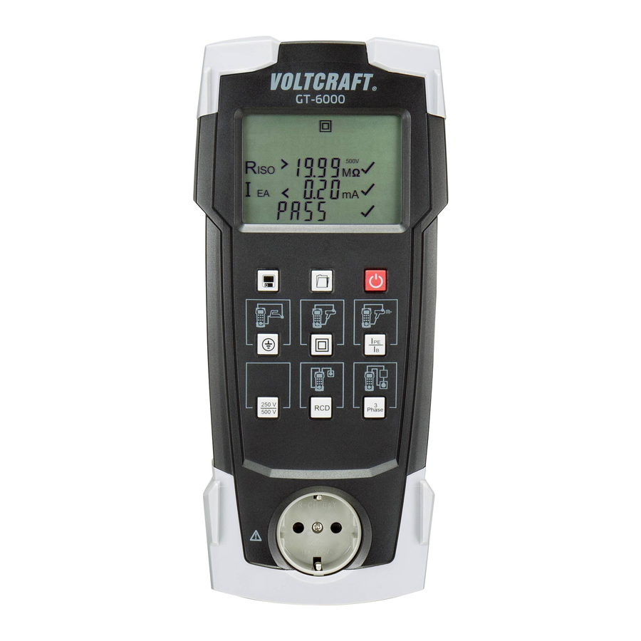
8. Operation elements and connections... - Page 9 1 Schuko test socket for connecting DUT 2 Pushbutton for testing class 1 (protection) devices (protective conductor and touchable conductive parts connected) 3 Pushbutton for testing class 2 type devices (devices without protective conductor and with accessible conductive parts) and for testing of class 3 type devices (safety low voltage) 4 Pushbutton for testing the protective conductor current (using differential measurement) or the contact current (using direct measurement) when DUT is supplied with 230 V AC 5 Insulation resistance measurement: pushbutton for setting the test voltage (250 V DC or 500 V DC)
- Page 10 LCD Symbols Warning, potentially dangerous voltage! Class I Test Class II Test Indication that long version of test is selected (protective conductor resistance, differential and touch leakage current measurements) Calibration mode (only available in service center) USB connection STORE (saving record in PAT memory) OPEN (recall saved record from PAT memory) Battery is low (battery replacement is required) Battery is empty (PAT will soon Turn Off)
- Page 11 Protective conductor resistance - R Test Insulation resistance – R Test Differential or Touch Leakage Current – I Test DIFF Substitute Leakage Current – I Test RCD Test Portable RCD Test RCD Test - 180° initial polarity RCD Test - 0° initial polarity Volt - Voltage measurement Ω...
- Page 12 Mili Ampere - Leakage Current Test Mili Second - RCD Test FAIL PASS Voltage measurement - LINE to NEUTRAL Voltage measurement - LINE to EARTH Voltage measurement - NEUTRAL to EARTH IEC Power Cable Test 3- Phase 16A CEE Adapter Note: Backlight function (white-LEDs) is activated/deactivated by short press to the pushbutton (15).
-
Page 13: Carrying Out Measurements
• Measurements have to be carried out by respecting the standards. a) Testing a mains power outlet • Press the red pushbutton (15) to switch on the GT-6000 v2. • To switch the device on or off, press and hold the button for approx. 1 second. The device will turn on or off with a beep. -
Page 14: B) Testing Devices Of Protection Class 1
• In mains mode (differential current measurement method is executed and tests the device under test during operation), connect the mains cable with the built-in connector (11) on the GT-6000 v2 and the safety plug to an earthed socket (230 V, 50 Hz, 16 A). 250 V... - Page 15 Protective conductor current (differential current measurement method) – Differential Leakage Current • After the R measurement GT-6000 v2 stops the test sequence and prompts the user to switch the mains voltage from 230 V to the test socket (“I ” symbol flashes).
- Page 16 • The protective conductor current measurement (Differential Leakage Current) starts by (short) pressing pushbutton (4) if the mains voltage is correct. Note: Extended version of this test is started by (long) press to the pushbutton (4). • During testing, DUT should be switched on and active. Step 1 (of 2): •...
-
Page 17: C) Testing Devices Of Protection Class 2 (Insulated) And Devices Of Protection Class 3 (Safety Low Voltage)
Option: Substitute Leakage Current (Battery operation, without mains supply): • Appliance is connected to the GT-6000 v2 like previously described (above), but without connecting the mains voltage. • If measured I (using equivalent leakage current measurement method) is lower than the permissible limit value, a tick symbol will be displayed beside I value. - Page 18 Contact current measuring using the direct measurement method (Touch Leakage Current) • After the R measurement GT-6000 v2 stops the test sequence and prompts the user to switch the mains voltage from 230 V to the test socket (“I ” symbol LEAK flashes).
-
Page 19: D) Lead Test - Testing Of Power / Extensions Cables, Cable Reels And Multi-Plugs
(protection class 3 objects), marked with X symbol beside Riso value, test person must decide about result. Option: Substitute Leakage Current (Battery operation, without mains supply): • Appliance is connected to the GT-6000 v2 like previously described (above), but without connecting the mains voltage. - Page 20 • R depends on the length and cross-section of the tested cable! • If R is higher than limit value (≤0.3 Ω up to a length of 5 m), but lower than 1 Ω, the measured value is displayed without rating. The “tAble” symbol is displayed, and the test sequence stops.
- Page 21 Testing extension cables, cable reels and multi-plugs • Connect the IEC power cable (from GT-6000 v2 kit), to the IEC low - power connector, IEC 60320 C14, (10). • Connect extension cable to the test socket (1) and to the safety plug on the IEC low-power cable.
-
Page 22: E) Testing (Passive And Active) Of Three-Phase Devices
Option Active testing • For active testing, adapter 16 A CEE, 5-pin (option in GT-6000 v2 kit), is necessary. • Adapter is active (electronics inside). • Connect the CEE connector on the device under test to the CEE connector on the measurement... -
Page 23: F) Testing Of Rcds
30 mA residual current circuit breakers RCCBs/RCDs • The GT-6000 v2 supports tripping time measurement of permanently installed RCCBs/RCDs and portable RCCBs/ PRCDs with a rated residual current of 30 mA. The tripping time is measured with 2 different current settings in the automatic test sequence: the single rated fault current (initial polarity 0°/180°) and the five-fold rated fault current... - Page 24 (200 ms). • If tripping time caused by the single rated fault current is inside limit, GT-6000 v2 will generate 150 mA fault current with 0° or 180° initial polarity. The RCCB/RCD is tripped, and the tripping times caused by this five-fold rated fault current will be measured.
- Page 25 • Tick symbol is displayed next to the tripping time value if the tripping time is less than the limit (200 ms). • If tripping time caused by the single rated fault current is inside limit, GT-6000 v2 will generate 150 mA fault current with 0°...
-
Page 26: Memory Function
Remove all connection cables and test objects from the GT-6000 v2. Only the interface cable may be connected. • The driver and the download program must be installed on the computer before the GT-6000 v2 can be connected via the USB interface. -
Page 27: E) Software And Driver Installation
USB interface on your computer. • Switch the GT-6000 v2 off. To activate the USB interface, press and hold the save button (13) and the On/Off button (15) at the same time. The device switches on and activates the interface. The USB plug symbol and “USB Conn”... -
Page 28: F) Setting The Rtc (Real Time Clock)
Setting the RTC (Real Time Clock) To set the date and time, proceed as follows: • Switch the GT-6000 v2 off. • To activate the date and time setting, press and hold the folder button (14) and the On/Off button (15) at the same time. -
Page 29: Maintenance
11. Maintenance • When using the instrument in compliance with the instruction manual, no special maintenance is required. Should operational problems occur during daily use, consulting service will be at your disposal, free of charge. If functional errors occur after expiration of warranty, our sales service will repair your instrument without delay. a) Cleaning •... -
Page 30: D) Fuse Replacement / Product Disposal
d) Fuse Replacement / Product Disposal • Prior to fuse replacement, ensure that device is disconnected from external voltage supply and the other connected instruments (such as UUT, control instruments, etc.) • Only use fuses as described in the technical data section! •... -
Page 31: Technical Data
12. Technical data Display ..............Liquid crystal display (LCD) Battery status display ........Battery Symbol appears (< 2,4V) Measurement category ........CAT II 300 V Pollution degree ..........2 Protection class ..........IP40 Power supply ............6 AA or LR06 batteries, 1.5 V Mains voltage ...........230 V AC, 50 Hz Dimensions (L x W x H) ........277 x 124 x 68 mm Weight ..............approx. - Page 32 Earth Continuity - Protective conductor resistance Measurement range Resolution Accuracy 0.05 Ω - 19.99 Ω 0.01 Ω ±(5% + 2) Test current: >200 mA into 2 Ω Open circuit voltage: <5 V Factory Set Pass/Fail Preset limit: ≤0.3 Ω (up to 5 m length) Insulation resistance Measurement range Resolution...
- Page 33 Differential Leakage Current- Protective conductor current (differential current measurement method) Measurement range Resolution Accuracy 0.25 mA - 19.99 mA 0.01 mA ±(5% + 2) Test voltage: 230 V ±10% Rated current: 16 A Max. breaking capacity: 3000 VA Max. lamp load: 1000 W Max.
- Page 34 RCD test - Tripping time of RCCB/RCD Measurement range Resolution Accuracy 10 ms - 500 ms 1 ms ±(5% + 2) Testing of current/polarity: 30 mA sinusoidal/0° and 180°, 150 mA sinusoidal /0° and 180° Factory Set Pass/Fail Preset limit: 200 ms (30 mA), 40 ms (150 mA) Leakage Current measurement with 3-phase adapter - Protective conductor current (direct measurement method with optional measurement adapters) Measurement range...
- Page 35 This is a publication by Conrad Electronic SE, Klaus-Conrad-Str. 1, D-92240 Hirschau (www.conrad.com). All rights including translation reserved. Reproduction by any method, e.g. photocopy, microfilming, or the capture in electronic data processing systems require the prior written approval by the editor. Reprinting, also in part, is prohibited. This publication represent the technical status at the time of printing.
Need help?
Do you have a question about the GT-6000 and is the answer not in the manual?
Questions and answers