Table of Contents
Advertisement
Advertisement
Table of Contents

Related Manuals for VOLTCRAFT 632 FG


Summary of Contents for VOLTCRAFT 632 FG
-
Page 2: Table Of Contents
INDEX PAGE 1. PRODUCT INTRODUCTION........................ 4 1-1 D ............................4 ESCRIPTION 1-2 F .............................. 4 EATURES 2. TECHNICAL SPECIFICATIONS ......................5 3. PRECAUTIONS BEFORE OPERATION..................... 7 3-1 U ....................... 7 NPACKING THE INSTRUMENT 3-2 C ......................7 HECKING THE OLTAGE 3-3 E ............................ - Page 3 SAFETY TERMS AND SYMBOLS These terms may appear in this manual or on the product: WARNING Warning statements identify condition or practices that could result in injury or loss of life CAUTION Caution statements identify conditions or practices that could result in damage to this product or other property. The following symbols may appear in this manual or on the product: DANGER ATTENTION...
- Page 4 FOR UNITED KINGDOM ONLY As the colours of the wires in main leads may not correspond with the colours marking NOTE identified in your plug/appliance, proceed as follows: This lead/appliance must only be wired by competent persons The wire which is coloured Green & Yellow must be connected to the Earth terminal WARNING marked with the letter E or by the earth symbol or coloured Green or Green &...
-
Page 5: Product Introduction
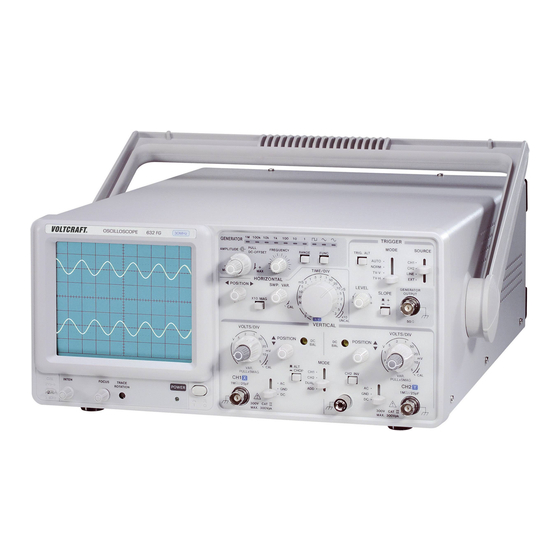
1. PRODUCT INTRODUCTION 1-1 Description The VOLTCRAFT 632FG oscilloscope + Function Generator is a portable-type, dual-channel oscilloscope with function generator. Its bandwidth of DC is up to 30MHz, and its maximum sensitivity is 1mV/DIV. The time base provides a maximum sweep time of 0.2uS/DIV. The sweep speed becomes 100nS/DIV after magnifying 10 times. -
Page 6: Technical Specifications
2. TECHNICAL SPECIFICATIONS MODEL VOLTCRAFT 632FG SPECIFICATIONS 30MHz OSCILLOSCOPE + FUNCTION GENERATOR 1. OSCILLOSCOPE 5mV ∼ 5V/DIV, 10 steps in 1-2-5 sequence. Sensitivity ≤3% ( × 5 MAG : ≤5%). Sensitivity Accuracy Vernier Vertical sensitivity To 1/2.5 or less of panel-indicated value. - Page 7 MODEL VOLTCRAFT 632FG SPECIFICATION 30MHz OSCILLOSCOPE + FUNCTION GENERATOR 0.2μSec ∼ 0.5 Sec/DIV, 20 steps in 1-2-5 sequence. Sweep Time ±3%. Sweep Time Accuracy Vernier Sweep Time ≤1/2.5 of panel-indicated value. Control HORIZIONAL Sweep Magnification 10 times (maximum sweep time 100nSec/DIV).
-
Page 8: Precautions Before Operation
3. PRECAUTIONS BEFORE OPERATION 3-1 Unpacking the instrument The product has been fully inspected and tested before shipping from the factory. Upon receiving the instrument, please unpack and inspect it to check if there is any damage caused during transportation. If any sign of damage is found, notify the bearer and/or the dealer immediately. -
Page 9: Panel Introduction
4. PANEL INTRODUCTION Fig. 4-1 Front Panel Fig. 4-2 Rear Panel 8 ... -
Page 10: Front Panel
4-1 Front Panel CRT : (6) POWER Main power switch of the instrument. Turn on the switch to light the LED (5). (2).INTEN Control the brightness of the spot or trace. (3) FOCUS Focus the trace to the sharpest image. (4) TRACE ROTATION Semi-fix potentiometer for aligning the horizontal trace in parallel with graticule lines. - Page 11 (28)LEVEL Display a synchronized stationary waveform and set a start point for the waveform. Toward “+” The trigger level moves upward on the display waveform. Toward “-” The trigger level moves downward on the display waveform. (25)TRIGGER MODE Trigger mode selection. AUTO If no trigger signal applied or the trigger signal frequency is less than 25Hz, the sweep will be in the free run mode.
-
Page 12: Rear Panel
4-2 Rear Panel Triggering: (24)EXT TRIG IN Input Terminal Input Terminal is used for external triggering signal by setting SOURCE switch (23) to the EXT position. (34)Z AXIS INPUT Input terminal for external intensity modulation signal. (35)CH1 SIGNAL OUTPUT Delivers a voltage of approximately 20mV/DIV from the CH1 signal to 50Ω terminal for frequency counting. AC POWER Input Circuit: (36)AC Power input connector Connect the AC power cord (supplied) to this connector. -
Page 13: Operation Method
5. OPERATION METHOD 5-1 Basic Operation---Single-channel Operation Before connecting the power cord to an AC line outlet, make sure that the AC line voltage input switch on the rear panel of the instrument is correctly set for the AC line voltage. After ensuring the voltage setting, set the switches and controls of the instrument as shown below: Item Setting... -
Page 14: Dual-Channel Operation
5-2 Dual-channel Operation Fig. 5-2 Set the VERT MODE switch to DUAL to display trace in CH2 (The procedure is same as CH1 described in previous section). At this step, the calibrator signal appears in CH1 is Square wave, but it appears in CH2 is a straight line as no signal applied to this channel yet. - Page 15 TV-H Set the MODE switch to TV-H mode and select horizontal sync pulses for sweep triggering to view composite video waveforms. Select horizontal sync pulses as a triggering to view horizontal lines of video. A sweep time of about 10 us/div is appropriate for displaying lines of video. Display the exact number of desired waveforms by setting SWP VAR control knob.
-
Page 16: Time/Div Control
(4) Function of TRIG ALT button: The TRIG ALT button is used to select alternate triggering and display the selected DUAL-trace of VERT MODE (the switch control knob CH1, CH2, DUAL and ADD modes). In the alternate trigger mode (when select dual-trace operation), the trigger source alternates between CH1 and CH2 with each sweep. -
Page 17: Calibration Of Probe
5-8 Calibration of Probe As explained previously, the probe makes up a wide range attenuator. Unless phase compensation is properly done, the displayed waveform will be distortion causing measurement errors. Therefore, the probe must be properly compensated before use. Connect 10:1 probe BNC to the INPUT terminal of CH1 or CH2 and set VOLTS/DIV switch at 50mV. Connect the probe tip to the calibration voltage output terminal and adjust the compensation trimmer on probe for optimum Square wave (minimum overshoot, rounding off and tilt). -
Page 18: Maintenance
6. MAINTENANCE WARNING The following instructions are executed by qualified personnel only. To avoid electrical shock, do not perform any servicing other than the operating instructions unless you are qualified to do so. 6-1 Fuse Replacement If the fuse blows, the power lamp indicators will not light and the instrument will not start. The fuse holder should not normally be opened unless a problem has been caused to the unit. -
Page 19: Block Diagram
7. BLOCK DIAGRAM 18 ...
Need help?
Do you have a question about the 632 FG and is the answer not in the manual?
Questions and answers