Table of Contents
Advertisement
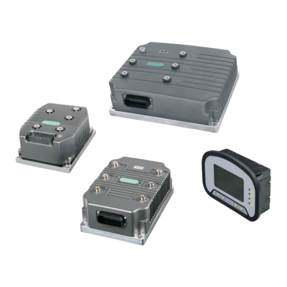
L6 Series Controller
Document Version:
Archive Date:
BOM Code:
Shenzhen Megmeet Drive Technology Co., Ltd. provides full technical support for our
customers,customers can contact local Megmeet offices or customer service centers, or
directly contact Megmeet headquarters.
Shenzhen Megmeet Drive Technology Co., Ltd.
All rights reserved. The contents in this document are subject to change without notice.
Shenzhen Megmeet Drive Technology Co., Ltd.
Address: 5th Floor, Block B, Unisplendor Information Harbor, Langshan Rd., Science &
Technology Park, Nanshan District, Shenzhen, 518057, China
Website: www.megmeet-drivetech.com
Tel: +86-755-86600500
Fax: +86-755-86600562
Service email: driveservice@megmeet.com
V1.0
2021/09/02
1
Advertisement
Table of Contents

Related Manuals for Megmeet L6 Series


Summary of Contents for Megmeet L6 Series
- Page 1 V1.0 Archive Date: 2021/09/02 BOM Code: Shenzhen Megmeet Drive Technology Co., Ltd. provides full technical support for our customers,customers can contact local Megmeet offices or customer service centers, or directly contact Megmeet headquarters. Shenzhen Megmeet Drive Technology Co., Ltd. All rights reserved. The contents in this document are subject to change without notice.
- Page 2 The relevant precautions during the installation, wiring, parameter setting, troubleshooting and daily maintenance will be detailed in this manual. To ensure the correct installation and operation of the L6 series controller as well as its high performance, please read carefully this user manual before installing the equipment.
- Page 3 We have implemented strict inspection on the manufacturing, package and delivery of the product. If there is any error, please contact us or your distributor immediately. We are engaged in the continuous improvement of controller. The relevant manuals provided by us are subject to change without prior notice.
- Page 4 ·When carrying the drive, protect the operation panel and the cover against any stress, otherwise, the drive may drop and cause human injury or property damage. ·Please install the controller on the place that can withstand the weight of the drive, otherwise, the drive may drop and cause human injury or property damage.
-
Page 5: Table Of Contents
3.5 LED interface definition............................32 Chapter 4 Parameter List....................... 33 4.1 Basic menu function code parameter table.......................33 Chapter 5 L6 Series Controller Debugging Steps..............59 5.1 L6 series controller installation preparation...................... 59 5.2 L6 series controller detection..........................59 5.3 L6 series controller debugging..........................61 5.4 Controller and motor matching..........................63... -
Page 6: Chapter 1 Introduction Of L6 Series Controller
Chapter 1 Introduction of L6 Series Controller Introduction This series of controller is a low voltage DC input, high current output AC motor controller, powered by a battery system, can be used in electric forklifts, battery touring buses, golf carts, lawn mowers, cleaning cars, AGV cars and various small passenger cars. -
Page 7: Product Series
Product series Table 1-1 Name and model of controller Output current Voltage Operating Power supply Cooling Model level voltage range starting voltage method rating 2 min 1 min 30 s hour Natural L632-2420 24VDC 20V~28V 150A 200A IP65 cooling Natural L632-2437 24VDC 20V~28V... -
Page 8: Technical Specifications Of Product
Water L650-5D90 500VDC 450V~600V 225A 450A IP67 cooling Water L650-5DB0 500VDC 450V~600V 300A 600A IP67 cooling Note: 96V and 144V models are being developed, * indicates that there is no such parameter. Technical specifications of product Table 1-2 Technical specifications of controller Control mode Closed loop vector, IF mode, VF mode Control... -
Page 9: Outline, Mounting Dimensions And Gross Weight Of Controller
pressure is 70~106kPa. Used at the place lower than 1000m (derated at the place above 1000m, derated 1% Altitude for every increase of 100m) Ambient -30℃~+50℃ (derated when used in the ambient temperature of 40℃~50℃) temperature Humidity 5%~95%RH, non-condensing Vibration Less than 9.8m/s (1g) Storage... - Page 10 Fig. 1-2 Outline, mounting dimensions of L636...
- Page 11 Fig. 1-3 Outline, mounting dimensions of L638...
- Page 12 Fig. 1-4 Outline, mounting dimensions of L640...
- Page 13 Fig. 1-5 Outline, mounting dimensions of L650 Table 1-3 Outline, mounting dimensions and gross weight Model Gross weight (kg) Dimension(mm) L632-2420 L632-2437 2.23 180*140*73.5 L632-4827 L632-4835 L636-4845 L636-8035 4.12 244*165*92 L636-8045 L636-9620 L636-1420 L638-4865 L638-8050 244*275*92 L638-8065 L638-9650...
-
Page 14: Megmeet Controller Instrumentation
322*242*271.5 L640-4D20 322*242*127.5 L640-4D30 322*242*131.5 L650-5D60 L650-5D90 11.5 417*280.4*175 L650-5DB0 Note: 96V and 144V models are being developed. MEGMEET controller instrumentation 1.7.1 Product model description 1.7.2 Product series Operating Voltage Operating Power supply Model IP rating ambient Cooling method level... - Page 15 Communication fault light Hand brake light Seat switch fault light Low battery fault light Cursor up Cursor down Enter the menu Back to previous menu level Description of fault light flashing Fault light Fault description Troubleshooting The communication between Communication fault Check whether the communication the instrumentation and the light flashing...
- Page 16 Communication with Communication with In hours the main drive pump drive High and low speed modes Battery level display Forward, backward and neutral position display Speed display Icon display bar 1. Battery level display, display value is 0% ~ 100%; 2.
- Page 17 Entry method: In the case of the main interface, press key once to enter the first-level menu. The first-level menu includes the “TESTER” and “SETTING” second-level menus. Exit method: Press once to exit the menu and return to the main interface. 2.
- Page 18 Entry method: In the case of the main interface, press once, then press ▼ again, move the cursor to SETTING, and then press to enter the hour meter clear input password interface, press ▲ key, enter the first password, and then press ▼ to enter into the second password change, input the four digit password in sequence, and press the confirm button to clear the hour meter.
- Page 19 1.7.7 Terminal definition Definition Description J1-PIN1 BATTERY+ Connect to battery positive, 18-90V DC input J1-PIN2 BATTERY- Connect to battery negative, 0V J1-PIN3 SENDER1 0-3.3V analog input J1-PIN4 SENDER2 0-3.3V analog input J1-PIN5 SENDER3 0-5V analog input J1-PIN6 SENDER4 0-5V analog input J1-PIN7 Switched-input1 Digital input 1, active high...
-
Page 20: Product Use Environment And Installation Requirements
J1-PIN18 SENDER 0-5V analog input J1-PIN19 J1-PIN20 Definition Description Communication with the drive CAN-H J2-PIN1 CAN-H Communication with the drive CAN J2-PIN2 CAN-L J2-PIN3 Connect to battery negative J2-PIN4 CAN communication terminal resistance strobe, short J2-PIN5 CAN-H with J2-PIN6 when needed CAN communication terminal resistance strobe, short J2-PIN6 CAN-TERM... - Page 21 • The wiring between the motor, battery and controller is as short as possible, and the connection should be parallel; • Small current cables should be kept away from large current cables and must be crossed in orthogonal directions; • The CAN communication bus must be twisted pair. We recommend twisted pair with shield. All switches must be in the disconnection position.
-
Page 22: Chapter 2 Wiring Of Controller
Chapter 2 Wiring of Controller This chapter introduces the wiring and cable connection of controller, as well as the issues needing attention. • Do not open the cover until the power supply of the controller is completely disconnected for at least 10 minutes. - Page 23 Table 2-1 L632 model main loop interface definition Terminal Function Controller positive bus input, connect the positive terminal of the battery Controller negative bus input, connect the negative terminal of the battery Motor U phase output Motor V phase output Motor W phase output Terminal type 2 Applicable models: L636 series...
- Page 24 Fig. 2-3 L638 model appearance Table 2-3 L638 model main loop interface definition Terminal Function Controller positive bus input, connect the positive terminal of the battery Controller negative bus input, connect the negative terminal of the battery Motor U phase output Motor V phase output Motor W phase output Terminal type 4...
- Page 25 Table 2-4 L640 model main loop interface definition Terminal Function Controller positive bus input, connect the positive terminal of the battery Controller negative bus input, connect the negative terminal of the battery Motor U phase output Motor V phase output Motor W phase output Terminal type 5 Applicable models: L650 series...
- Page 26 2.1.2 Wiring for basic operation CN 1-1 CN 1-13 CN 1-22 COIL RETURN CN 1-33 CN 1-24 CN 1-9 CN 1-6 CN 1-10 DRIVER 1 CN 1-5 CN 1-11 DRIVER 2 CN 1-4 DRIVER 3 CN 1-12 CN 1-3 DRIVER 4 CN 1-14 CN 1-2 PROP.DRIVER...
-
Page 27: Wiring And Configuration Of Control Circuit
Wiring and configuration of control circuit 10 11 12 13 14 15 16 17 18 19 20 21 22 23 24 25 26 27 28 29 30 31 32 33 34 35 Fig.2-7 Terminal interface definition diagram For the terminal function description, please refer to Table 2-6. Table 2-6 35PIN control interface definition 35PIN control interface definition Terminal... - Page 28 current 12A Speed cutting SW16 Digital input, 0/48V or 80V, active high switch THR_HI Throttle power + Allowable maximum current: 100mA Provide +5V power for external load Input voltage range:0~5V (input Accept analog voltage single-ended THR WIPER Throttle signal resistance: 4.9kΩ) input Input voltage range:0~5V (input Accept analog voltage single-ended...
- Page 29 CAN L matching CAN_T_L resistor CAN L CAN L(1M) Note It is suggested to use the wire with cross section area over 1mm as the connecting wire of the control circuit terminals. Use shielded wires for motor encoder signal wires.
-
Page 30: Chapter 3 Quick Operation Guide For Controller
Chapter 3 Quick Operation Guide for Controller Controller operation panel Fig. 3-1 Schematic diagram of operation panel LED description Table 3-1 LED description LED symbol Name Meaning Color On: Current parameter displayed represents the running frequency Frequency LED Green Flash: Current parameter displayed represents the frequency set On: Current parameter displayed represents Current LED... -
Page 31: Introduction To Operation Panel Keys
On: In the stop status, it means the controller has forward running command In the running status, it means the Forward running LED Green controller is running forward Flash: The controller is switching from FWD to On: In the stop status, it means the controller has reverse running command Status In the running status, it means the... -
Page 32: Identification Of Led Display Symbols
Name Function start to run STOP/RESET Stop/reset key Stop or fault reset Identification of LED display symbols The correspondence relation between the LED display symbols and the character/figure is as shown below: LED interface definition The keyboard is connected through the network cable. If it is not convenient to make the 35PIN terminal wire into crystal connector, you can make the adapter. -
Page 33: Chapter 4 Parameter List
Chapter 4 Parameter List Explanation to the terms in the function code parameter table Table field Explanation Function code Representing the number of the function code, e.g. P00.00 number Function code Name of the function code, explaining it name Leave-factory The value of the function code after restoring the leave-factory settings value Set range... - Page 34 modified 0: Left drive Controller type 1: Right drive P00.07 × 2: Pump drive 2420: 24V 200A 2437: 24V 375A 4827: 48V 270A 4835: 48V 350A Model setting P00.08 4845 × 4845: 48V 450A 4860: 48V 600A 8035: 80V 350A 1420: 144V 200A Group P01: Display parameters Output...
- Page 35 Frequency P02.05 keyboard 0.--3000.00 ○ reference Downtime P02.06 confirmation 0.--65535 ○ time Maximum P02.09 output 0.--1000.00 × frequency Group P03: Motor parameters Rated power of P03.00 1.--400.00 ○ motor Rated voltage P03.01 1.--999.9 ○ of motor Rated current P03.02 0.1--999.9 ○...
- Page 36 coefficient Synchronous 0.--0xFFFF P03.26 motor initial ○ angle 0.001~100 P03.27 Slip gain ○ Phase sequence of 0: Power line phase sequence OK motor power 1: Restart the machine after replacing any P03.28 line after × synchronous two-phase power line phase sequence machine identification IPM motor...
- Page 37 Backward 0.0~3000.0 acceleration P04.03 ○ time Deceleration time when the accelerator 0.0~3000.0 P04.04 ○ pedal is fully released when reversing Deceleration time when the accelerator 0.0~3000.0 P04.05 ○ pedal is not released when reversing Forward and backward switch to 0.0~3000.0 P04.06 ○...
- Page 38 Mechanical 0 -- 65535 braking speed P05.05 ○ loop gain Integral time of electromagnetic 0.1M 0 -- 65535 P05.06 ○ brake speed loop Climbing speed 50 -- 100 P05.07 ○ limit Climbing speed 0 -- 65535 P05.08 1000 ○ stable Kp gain Climbing speed 0 -- 65535 P05.09...
- Page 39 release filter time High speed electromagnetic braking 0 -- 65535 P05.24 1500 ○ deceleration time when moving forward Low speed electromagnetic braking 0 -- 65535 P05.25 2500 ○ deceleration time when moving forward Accelerator enable switch 0 -- 65535 P05.26 ○...
- Page 40 line 1: Enable disconnection detection enable switch Accelerator pedal/tire angle 0: Disable abnormality P07.02 × 1: Enable detection enable switch HPD fault 0: Disable P07.03 × enable switch 1: Enable Hour meter 0: Disable P07.04 × clear switch 1: Enable Flux-weakening 0: Disable control enable...
- Page 41 Motor speed 0: Disable P07.14 protection × 1: Enable switch Pump drive 0: Disable proportional P07.15 × valve input 1: Enable enable switch Mechanical 0: Automatic P07.16 brake control × 1: Manual mode Tire angle 0: Disable P07.17 sensor enable ×...
- Page 42 Tire angle sensor value in the middle of 0.-- 3300.mv P08.06 × the steering wheel Tire angle sensor value when the right 0.-- 3300.mv P08.07 × side of the steering wheel is limited Accelerator pedal corresponds to 0.-- 3300mv P08.08 ×...
- Page 43 is killed Battery voltage 0 -- 1000 P08.17 × level BMS type 0 -- 10 P08.18 × 0: Ht 1: Dsl Vehicle tire 0.0 -- 6000.0 P08.19 ○ diameter Vehicle 0.0 -- 6000.0 P08.20 22.6 ○ gearbox ratio 0 -- 5 0: No instrumentation Dial type P08.21...
- Page 44 definition, effective after restart Input polarity setting: 0-1 0: Indicates that the input is valid when it is low. SW1 terminal P09.01 × logic selection 1: Indicates that the input is valid when it is high. Effective after restart Input function code: 1-32 SW3 terminal 0: No definition P09.02...
- Page 45 Input function code: 1-32 SW8 terminal 0: No definition P09.12 function × 1-32: FunIN.1-32, refer to DIDO function code selection definition, effective after restart Input polarity setting: 0-1 0: Indicates that the input is valid when it is low. SW8 terminal P09.13 ×...
- Page 46 selection 1-32: FunOUT.1-32, refer to DIDO function code definition Output polarity setting: 0-1 0: Indicates that the output is low when it is DR5 terminal P10.07 valid. × logic selection 1: Indicates that the output is high when it is valid.
- Page 47 Output frequency when P10.18 DR5 is used as 1.--50000 × a proportional valve Output duty cycle when P10.19 DR5 is used as 0.0--100.0 × a proportional valve Group P12: Advanced function parameters Current loop P12.00 proportional 0.000 -- 65.535 ○ gain Current loop P12.01...
- Page 48 suppression point Medium and low frequency braking 0 -- 1000 P12.13 × overcurrent suppression point Low frequency torque 0.01 0 -- 65535 P12.14 ○ reference filtering time Torque limiting curve P12.15 0.0 -- 300.0 ○ frequency point Torque limiting P12.16 curve 0.0 -- 100.0 ○...
- Page 49 depth Output voltage P12.27 0 -- 1 × mode Synchronous P12.28 machine weak 0. -- 2 × magnetic mode Synchronous machine model calculates field P12.29 weakening 0.0 -- 5.0 ○ current adjustment coefficient Asynchronous machine field P12.30 50 -- 200 ○...
- Page 50 slope Steep slope slowly P13.10 0.1 -- 6553.5 ○ descending Kp gain Slope speed P13.11 1 -- 3000 ○ Slope Kp gain P13.12 0.1 -- 6553.5 ○ Steep slope slowly P13.13 0.001 -- 65.535 0.01 ○ descending Ki gain Group P14: Manufacturer parameters Weak magnetic P14.02 56.7 -- 100.0...
- Page 51 Fault output lamp flashing P14.14 0 -- 65535 ○ frequency Cutting speed switch switching P14.15 0 -- 65535 ○ smoothing factor Fault output long signal P14.16 0 -- 65535 ○ length Group P16: Analog configuration Throttle depth 1/ pump drive 0.0 -- 100.0 P16.00 ○...
- Page 52 3 / frequency corresponding to pump drive up and down analog 3 Throttle depth 4/ pump drive 0.0 -- 100.0 P16.06 ○ up and down analog 4 Frequency corresponding to throttle depth 4/ frequency 0.0 -- 100.0 P16.07 ○ corresponding to pump drive up and down analog 4...
- Page 53 Pump drive 0.0 -- 100.0 side shift P16.16 ○ analog 1 Frequency corresponding to pump drive 0.0 -- 100.0 P16.17 ○ side shift analog 1 Pump drive side shift 0.0 -- 100.0 P16.18 ○ analog 2 Frequency corresponding to pump drive 0.0 -- 100.0 P16.19 ○...
- Page 54 pump drive accessory 1 frequency Switch valve pump drive 0.0 -- 100.0 P16.29 ○ accessory 2 frequency Proportional valve analog 0 -- 4096 P16.30 ○ input enable threshold Group P17: Reserved function Excitation adjustment 0 -- 60000 2000 P17.05 ○ proportional gain (reserved) Excitation...
- Page 55 deceleration time curve & throttle depth 1 Throttle depth/ acceleration/de celeration time curve & 0.0 -- 1.0 P18.30 ○ acceleration/ deceleration time percentage 1 Throttle depth / acceleration / deceleration 0.0 -- 100.0 P18.31 ○ time curve & throttle depth 2 Throttle depth/ acceleration/ deceleration...
- Page 56 detection coefficient Analog value when the 0 -- 4095 P18.46 throttle is enabled Accelerator P18.48 pedal stepping 0 -- 100 ○ threshold Accelerator P18.49 pedal stop 0 -- 100 ○ threshold Accelerator pedal stepping P18.50 0 -- 65535 ○ detection refresh time Steering wheel P18.51...
- Page 57 third (last) fault Output terminal P20.09 status at the third (last) fault Drive status at P20.10 the third (last) fault Power-on time P20.11 at the third (last) fault (min) Running time at P20.12 the third (last) fault (min) Frequency at P20.13 the second fault Current at the...
- Page 58 Power-on time P20.27 at the first fault (min) Running time at P20.28 the first fault (min) Group P98: Parameter sampling Current sampling 0.0--2000.0 P98.06 × coefficient Note: ○: Means the function code can be changed during running; ×: Means the function code can be changed in the stop state; *: Means the function code can be read only, can not be changed.
-
Page 59: Chapter 5 L6 Series Controller Debugging Steps
Chapter 5 L6 Series Controller Debugging Steps 5.1 L6 series controller installation preparation 1. Handheld controller: This is an optional device, mainly used for initial debugging of machine parameters, which can provide demand to the manufacturer. 2. Accelerator: Type Description Single-ended 0 –... - Page 60 All external wiring of the controller must be removed before testing, and the B+ and B- terminals should be discharged with a resistor of not less than 20Ω/30W! 5.2.2 Vehicle parameter detection L6 series controller provides a powerful PC inspection system that monitors the vehicle's various conditions in real time: Specifications...
-
Page 61: L6 Series Controller Debugging
The drive wheel of the vehicle must be suspended before the test to prevent accidental movement of the vehicle from causing human injury! 5.3 L6 series controller debugging 5.3.1 Voltage level setting 1) Use the controller operation panel to enter the P00.08 parameter group;... - Page 62 5.3.3 Electromagnetic brake parameter setting 1) Use the controller operation panel to enter the P05.17 parameter group; 2) Set the corresponding parameters according to the electric brake specifications. 5.3.4 Accelerator parameter setting 1) Suspended vehicle drive wheel; 2) Use the controller operation panel to enter the P08.08~P08.10 parameter group; 3) Set the corresponding parameters according to the accelerator parameters.
-
Page 63: Controller And Motor Matching
2) Use the controller operation panel to enter the P06 parameter group; 3) Enter the parameters in the selected mode, and adjust the torque of the walking motor and pump motor according to the load condition to achieve the best effect. Controller and motor matching 5.4.1 Motor matching If you are debugging a traction motor... -
Page 64: Measurement
10) Enter the forward and negative speed limits, P06.05, P06.06. Set to low torque to reduce the heat of the motor and the resonance of large current; 11) Check whether there is a fault alarm; Do not approach the wheel, the motor will start to rotate next! 12) Set the controller to the forward state;... -
Page 66: Chapter 6 Troubleshooting
The machine is malfunctioning The indicator light is always on The machine is running normally Alarm code table All the possible alarm types for L6 series controller are summarized as shown in table 6-2. Table 6-2 Alarm code table Alarm Alarm type... -
Page 67: Fault Code Table
Fault code table This fault code table provides the following information. • Fault code • The name of the fault displayed on the programmer • Performance caused by fault • Possible fault cause • Deep cause of fault • State resolution When a fault occurs, if it is confirmed that it is not a wiring error or a mechanical fault of the vehicle, try restarting with the vehicle key switch. - Page 68 Fault code displayed Fault on the Fault type Possible fault cause Solutions code instrumentation Check whether the power supply Abnormal power supply Er.014 0X16 Charging failure wiring and terminal wiring are wiring and terminal wiring correct Main contactor pull-in Check whether the contactor is Er.015 0X01 Contactor short circuit fault...
-
Page 69: Dido Function Definition
Fault code displayed Fault on the Fault type Possible fault cause Solutions code instrumentation 1. Encoder parameters are set incorrectly. 1. Set the encoder parameters Excessive speed correctly Er.037 2. No parameter deviation identification was 2. Identify motor parameters conducted Acceleration / deceleration Increase acceleration / deceleration Er.038... - Page 70 Table 6-4 DIDO function definition DIDO Coding Name Function name Status description FunIN.1 ForwardSW Forward switch Distribution FunIN.2 BackwardSW Back switch Distribution FunIN.3 SeatSW Seat switch Distribution FunIN.4 HandBrakeSW Hand brake switch Distribution FunIN.5 BrakeSW Foot brake switch Distribution FunIN.6 AccSW Throttle enable switch Distribution...
-
Page 71: Appendix 1 Precautions
Appendix 1 Precautions Please read the following carefully before using the product (if you have any questions, please contact MEGMEET engineers): If the following conditions occur, the controller may be seriously damaged! Danger 严 禁 产 品 进 水 Danger 严... - Page 72 严 禁 Danger 极 性 接 反 Danger 严 禁 电 机 短 路...
-
Page 73: Appendix 2 Warranty And Service
(such as unsatisfactory performance and function), please contact your product agent or Shenzhen Megmeet Drive Technology Co., Ltd.. 2). In case of any abnormality, please timely contact your product provider or Shenzhen Megmeet Drive Technology Co., Ltd. for help. - Page 74 Shenzhen Megmeet Drive Technology Co., Ltd. Shenzhen Megmeet Drive Technology Co., Ltd. Controller Warranty Bill Controller Warranty Bill Customer company: Customer company: Detailed address: Detailed address: Postal Code: Contact: Postal Code: Contact : Tel: Fax: Tel: Fax: Machine model: Machine model: Power: Machine No.:...
Need help?
Do you have a question about the L6 Series and is the answer not in the manual?
Questions and answers