EXFO FIP-400B User Manual
Fiber inspection probe and connectormax2
Hide thumbs
Also See for FIP-400B:
- User manual (103 pages) ,
- User manual (163 pages) ,
- User manual (142 pages)
Table of Contents
Advertisement
Quick Links
Advertisement
Table of Contents

Related Manuals for EXFO FIP-400B


Summary of Contents for EXFO FIP-400B
- Page 1 User Guide FIP-400B Fiber Inspection Probe and ConnectorMax2...
- Page 2 EXFO Inc. (EXFO). Information provided by EXFO is believed to be accurate and reliable. However, no responsibility is assumed by EXFO for its use nor for any infringements of patents or other rights of third parties that may result from its use.
-
Page 3: Table Of Contents
Contents Certification Information ......................v 1 Introducing the FIP-400B Fiber Inspection Probe and ConnectorMax2 ..1 Probe ............................1 Available Models ........................2 Probe Tips ..........................3 LED Indicator ..........................4 ConnectorMax2 Software .......................5 Conventions ..........................6 2 Safety Information ..................7 3 Setting up Your Fiber Inspection Probe and ConnectorMax2 ....9 Changing the Fiber Inspection Probe Tip ................9... - Page 4 Viewing Online Help ......................87 Transportation ........................87 7 Warranty ......................89 General Information ......................89 Liability ..........................90 Exclusions ..........................90 Certification ..........................90 Service and Repairs .......................91 EXFO Service Centers Worldwide ..................92 A Technical Specifications ................93 B Fiber Inspection Probe Tip Compatibility Chart ........95 Index .........................99 FIP-400B...
-
Page 5: Certification Information
European Community Declaration of Conformity An electronic version of the declaration of conformity for your product is available on our website at www.exfo.com. Refer to the product’s page on the Web site for details. Fiber Inspection Probe... -
Page 7: Introducing The Fip-400B Fiber Inspection Probe And Connectormax2
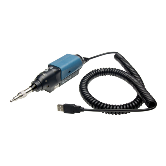
Introducing the FIP-400B Fiber Inspection Probe and ConnectorMax2 The FIP-400B Fiber Inspection Probe is a portable video microscope used to inspect fiber ends. Unlike traditional microscopes, the FIP-400B facilitates the examination of patchcord connectors and also hard-to-reach connectors on the back of patch panels and bulkhead adapters. -
Page 8: Available Models
Introducing the FIP-400B Fiber Inspection Probe and ConnectorMax2 Available Models The retaining nut holds tips securely in place, ensuring they are always fastened in the correct position. The status LED gives you information about the probe or the analysis ... -
Page 9: Probe Tips
Introducing the FIP-400B Fiber Inspection Probe and ConnectorMax2 Probe Tips Probe Tips The FIP-400B comes with two interchangeable tips included in two different packages (UPC or APC). Additional models are also available. UPC package: FIPT-400-FC-SC: FC-SC Bulkhead tip ... -
Page 10: Led Indicator
Introducing the FIP-400B Fiber Inspection Probe and ConnectorMax2 LED Indicator LED Indicator The LED located on the probe gives you information about the probe or the analysis results. Status Flashing blue Detection of the probe in progress Analysis in progress ... -
Page 11: Connectormax2 Software
Introducing the FIP-400B Fiber Inspection Probe and ConnectorMax2 ConnectorMax2 Software ConnectorMax2 Software ConnectorMax2 is the application used to view the fiber inspections. You can also use specific test configurations and analyze the fibers automatically upon capturing a picture. This application is available on the MAX-FIP Viewer. -
Page 12: Conventions
Introducing the FIP-400B Fiber Inspection Probe and ConnectorMax2 Conventions Conventions Before using the product described in this guide, you should understand the following conventions: ARNING Indicates a potentially hazardous situation which, if not avoided, could result in death or serious injury. Do not proceed unless you understand and meet the required conditions. -
Page 13: Safety Information
Safety Information ARNING Do not install or terminate fibers while a light source is active. Never look directly into a live fiber and ensure that your eyes are protected at all times. ARNING The use of controls, adjustments and procedures, namely for operation and maintenance, other than those specified herein may result in hazardous radiation exposure or impair the protection provided by this unit. - Page 14 -40 °C to 70 °C (-40 °F to 158 °F) Relative humidity 0 % to 95 % non-condensing Maximum operation 2000 m (6562 ft) altitude Pollution degree Overvoltage category Equipment should be normally protected against exposure to direct sunlight, precipitations and full wind pressure. FIP-400B...
-
Page 15: Setting Up Your Fiber Inspection Probe And Connectormax2
Setting up Your Fiber Inspection Probe and ConnectorMax2 You can change various settings in ConnectorMax2 such as the default storage location or the automated file name. These settings are stored for each user and kept for future work sessions. Changing the Fiber Inspection Probe Tip You can use various tips depending on the type of connector you are inspecting. -
Page 16: Adjusting Brightness
(except on a MAX-700B) when you log in or log out of a session (except on a MAX-700B) To adjust brightness: 1. In Live video mode, tap the button to switch to video settings mode. Brightness button FIP-400B... - Page 17 Note: The application returns to the FIP controls default mode after 10 seconds of inactivity. Note: To optimize the analysis of the connector, EXFO recommends to set the brightness to Auto most of the time. When the brightness level is different than 50 %, the Automatic button appears.
-
Page 18: Setting Up Autonaming
For example, if you have a file name with the Location, Cable and Fiber identifiers, in that order, the first item to be incremented is the Fiber identifier, then Cable, then Location: Location 1, Cable 1, Fiber 1 Location 1, Cable 1, Fiber 2 FIP-400B... - Page 19 Setting up Your Fiber Inspection Probe and ConnectorMax2 Setting up Autonaming Location 1, Cable 2, Fiber 1 Location 1, Cable 2, Fiber 2 and so forth. For multifibers, when several identifiers for the filename are selected, they appear sequentially in the order you have set. However, only one increment can be used to create a multifiber set of captures.
- Page 20 Setting up Your Fiber Inspection Probe and ConnectorMax2 Setting up Autonaming To configure the automatic file naming: 1. From the Main Menu, tap Identification. 2. From the Apply to list, ensure that Next capture or Current and Next capture is selected. FIP-400B...
- Page 21 Setting up Your Fiber Inspection Probe and ConnectorMax2 Setting up Autonaming 3. Enter all the information as follows: 3a. Locate the row corresponding to the identifier that you want to modify. If an identifier is marked with an icon, a predefined list with choices is available.
- Page 22 4. If you want to increment automatically the cable ID, the fiber ID, the location (A and/or B), the Connector ID, or the Frame, proceed as follows: 4a. Tap the Increment button. 4b. In the Increment window, select the Auto Increment check box corresponding to the identifier you want to increment. FIP-400B...
- Page 23 Setting up Your Fiber Inspection Probe and ConnectorMax2 Setting up Autonaming 4c. Enter the start, stop and increment values as desired. Note: The identifiers are processed in order, from the one with the largest indentation to the one with the smallest. For a given identifier, when the increment value reaches the stop value, the incrementation automatically switches to the next identifier.
- Page 24 6. Tap OK to confirm your new settings and to return to the main window. The new settings will apply the next time you perform a capture. FIP-400B...
- Page 25 Setting up Your Fiber Inspection Probe and ConnectorMax2 Setting up Autonaming To clear the values: 1. From the Main Menu, tap Identification. 2. In the Apply to list, select Next capture. 3. Tap the Clear Values button. 4. Tap OK to return to the main window. All values in the Value column are erased from the white boxes.
-
Page 26: Managing And Selecting Test Configurations
Creating custom test configurations is done through duplicating an existing configuration, and then modifying the desired criteria. If you create configurations on one unit or computer, and want to transfer them to another unit or computer, you can do so. FIP-400B... - Page 27 Setting up Your Fiber Inspection Probe and ConnectorMax2 Managing and Selecting Test Configurations To select a test configuration: 1. From the Main Menu, select Test Config. 2. Select FIP . Fiber Inspection Probe...
- Page 28 3. If necessary, in the Apply to list, select Next capture. 4. Choose the type of connector you want to use and tap the button at the end of the row. 5. In the list of available test configurations, select the configuration you want to use and tap OK. FIP-400B...
- Page 29 Setting up Your Fiber Inspection Probe and ConnectorMax2 Managing and Selecting Test Configurations To create a test configuration: 1. From the Main Menu, select Test Config. 2. Select FIP . Fiber Inspection Probe...
- Page 30 4. Choose the type of connector you want to use and tap the button at the end of the row. 5. Select the row corresponding to the configuration that is the closest to the one you want to create, then tap Duplicate. FIP-400B...
- Page 31 Setting up Your Fiber Inspection Probe and ConnectorMax2 Managing and Selecting Test Configurations 6. If you want to modify the general information, proceed as follows: 6a. In the Configuration Details window, tap the button at the end of the Properties row. 6b.
- Page 32 Note: When you duplicate and edit a test configuration, you cannot change the connector type field. 6c. Tap OK to confirm your choice and close the window. Use the Config. Details arrow to go back to the Configuration Details window and configure other parameters. FIP-400B...
- Page 33 Setting up Your Fiber Inspection Probe and ConnectorMax2 Managing and Selecting Test Configurations 7. If you want to modify the information about the inspection zones, proceed as follows: 7a. Tap the button corresponding to the desired inspection zones. 7b. Modify the parameters as needed to indicate whether you want to be notified of scratches, defects or both for each zone in the fiber, then set thresholds for each item you select.
- Page 34 Details window and configure other parameters. 8. If necessary, use the Config. Details arrow to go back to the Configuration Details window and tap OK to close the window. Use the FIP Config. arrow to go back to the FIP configuration list. FIP-400B...
- Page 35 Setting up Your Fiber Inspection Probe and ConnectorMax2 Managing and Selecting Test Configurations To edit a test configuration: 1. From the Main Menu, select Test Config. 2. Select FIP . Fiber Inspection Probe...
- Page 36 5. Select the configuration you want to edit and tap the button at the end of the row. Note: You cannot edit standard test configurations. 6. Change the criteria as required. For details, see the section on creating a test configuration. FIP-400B...
- Page 37 Setting up Your Fiber Inspection Probe and ConnectorMax2 Managing and Selecting Test Configurations To delete a test configuration: 1. From the Main Menu, select Test Config. 2. Select FIP . Fiber Inspection Probe...
- Page 38 3. If necessary, in the Apply to list, select Next capture. 4. Choose the type of connector you want to use and tap the button at the end of the row. MPORTANT The application will not prompt you for confirmation before deleting a configuration. FIP-400B...
- Page 39 Setting up Your Fiber Inspection Probe and ConnectorMax2 Managing and Selecting Test Configurations 5. Select the row corresponding to the configuration you want to remove, then tap Delete. Note: You cannot delete standard test configurations. Fiber Inspection Probe...
- Page 40 Setting up Your Fiber Inspection Probe and ConnectorMax2 Managing and Selecting Test Configurations To import test configurations: 1. From the Main Menu, select Test Config. 2. Select FIP . FIP-400B...
- Page 41 Setting up Your Fiber Inspection Probe and ConnectorMax2 Managing and Selecting Test Configurations 3. Choose the type of connector you want to use and tap the button at the end of the row. 4. From the FIP Configuration window, tap Import. Fiber Inspection Probe...
- Page 42 Setting up Your Fiber Inspection Probe and ConnectorMax2 Managing and Selecting Test Configurations 5. From the Open dialog box, select the file you want to import. 6. Tap OK to close the window. FIP-400B...
- Page 43 Setting up Your Fiber Inspection Probe and ConnectorMax2 Managing and Selecting Test Configurations To export test configurations: 1. From the Main Menu, select Test Config. 2. Select FIP . Fiber Inspection Probe...
- Page 44 3. Choose the type of connector you want to use and tap the button at the end of the row. 4. From the FIP Configuration window, select the row corresponding to the test configuration you want to export. Note: You cannot export standard test configurations. 5. Tap Export. FIP-400B...
- Page 45 Setting up Your Fiber Inspection Probe and ConnectorMax2 Managing and Selecting Test Configurations 6. From the Save As dialog box, select the folder where you want to export your file. 7. If desired, modify the file name. 8. Tap OK to close the window. Fiber Inspection Probe...
-
Page 46: Editing The Power Meter Test Configurations
Values that are greater than the predefined thresholds are displayed in white on a red background. Values that are pass are displayed in green. To edit the power meter test configurations: 1. From the Main Menu, select Test Config. FIP-400B... - Page 47 Setting up Your Fiber Inspection Probe and ConnectorMax2 Editing the Power Meter Test Configurations 2. Select Power Meter. 3. In the Apply to list, select Next capture. 4. Select the desired wavelength. 5. Set the pass/fail thresholds for the selected wavelength. Note: You can apply the settings to all wavelengths.
-
Page 48: Reverting To Factory Settings
(Pass/Fail status) option. Reverting to Factory Settings At any time in the application, you can revert to factory settings in your menus. However, the Restore to Factory Settings button is valid only for the window or tab where you use it. FIP-400B... -
Page 49: Changing Fiber Information Of Existing Captures
Setting up Your Fiber Inspection Probe and ConnectorMax2 Changing Fiber Information of Existing Captures Changing Fiber Information of Existing Captures It is possible to modify the information for an existing capture. This information is provided by the automatic file naming. The procedure is almost the same as the one for autonaming but the changes apply to the current capture only. -
Page 51: Inspecting Fiber Ends
Inspecting Fiber Ends (Single Fiber and Transceiver - Fiber Receptacles) When you connect the FIP-400B Fiber Inspection Probe to your unit, you can view and inspect fiber ends right away. This direct viewing mode is known as the Live mode. - Page 52 1. Install a probe tip (see Changing the Fiber Inspection Probe Tip on page 9). 2. Insert the fiber into the probe tip. 3. Connect your Fiber Inspection Probe to your unit. On an FTB-500, connect the probe to the lower USB port located on the front of the unit. FIP-400B...
- Page 53 Inspecting Fiber Ends Inspecting Fiber Ends (Single Fiber and Transceiver - Fiber Receptacles) 4. Start ConnectorMax2 if it is not already started. 5. Ensure to configure the automatic file naming (see Setting up Autonaming on page 12). 6. Choose the type of connector you want to use (SF or Transceiver). Fiber Inspection Probe...
- Page 54 8. If the fiber end is dirty, remove it from the probe, clean it and reinspect it. 9. Once you are satisfied with the inspection, when in high magnification level, press Capture. Press the Fiber Inspection Probe handset button. 10. Go to the next connector or close the application. FIP-400B...
-
Page 55: Setting Up Multifiber Inspection
Inspecting Fiber Ends Setting Up Multifiber Inspection Setting Up Multifiber Inspection Inspecting and analyzing multifiber connectors can be done separately for each fiber, or as a batch. When the inspection and the analysis are done separately, there is a transition between the Live Video mode and the Capture mode after an image is captured. -
Page 56: Displaying Multifiber Connector Overlay
Note: The FIP-410B probe does not display the overlay in multifiber. To display the multifiber connector overlay: 1. From the main window, select User Preferences. 2. Select the MF Connector tab. 3. Choose Include multifiber connector overlay. 4. Tap OK to confirm your choice and close the window. FIP-400B... -
Page 57: Inspecting Fiber Ends (Multifiber)
Inspecting Fiber Ends Inspecting Fiber Ends (Multifiber) In the main window, a blue arrow now indicates the fiber under test. Inspecting Fiber Ends (Multifiber) The multifiber inspection with a FIP-430B probe allows you to see multiple fibers at a time. You can capture images of your inspections to include in reports, or save them for future analyses. - Page 58 With this feature, all fibers are captured and previewed one after another for a configured period of time. Then the analysis is launched when all fibers are inspected. For more information on analysis, see Analyzing Captures on page 64. FIP-400B...
- Page 59 Inspecting Fiber Ends Inspecting Fiber Ends (Multifiber) To inspect fiber ends (multifiber) in Live mode: 1. Install a probe tip (see Changing the Fiber Inspection Probe Tip on page 9). 2. Insert the fiber into the probe tip. 3. Insert replaceable APC or UPC nozzle in and tighten it (turn clockwise).
- Page 60 6. Start ConnectorMax2 if it is not already started. 7. Ensure to configure the automatic file naming (see Setting up Autonaming on page 12). 8. Choose the type of connector you want to use (MF). Tap File, then New. FIP-400B...
- Page 61 Inspecting Fiber Ends Inspecting Fiber Ends (Multifiber) 9. Choose the type of connector you want to use between MTP/MPO (selected by default) or Optitap. 10. Depending on the probe you are using, proceed as follows: If you have an FIP-420B, activate the auto centering. ...
- Page 62 13. Center the appropriate connector in the array: For multi-row tips, use the Y wheel to select the required fiber row. For multi-row and single-row tips, use the X wheel to select the required fiber. X wheel Y wheel FIP-400B...
- Page 63 Inspecting Fiber Ends Inspecting Fiber Ends (Multifiber) 14. View results on screen. Note: The auto-focus starts automatically only for the first fiber (FIP-430B only). Hold the magnification control button located on the probe for one second to reactivate the auto-focus process (FIP-430B only). Adjust focus manually.
-
Page 64: Retesting A Fiber (Multifiber)
In order to avoid this incrementation and end up with unwanted files, you can test a fiber again. To retest a fiber in Live Video mode: 1. Use the list to navigate between the captured fibers. 2. Tap Capture. FIP-400B... - Page 65 Inspecting Fiber Ends Retesting a Fiber (Multifiber) To retest a fiber in Capture mode: 1. Use the list to navigate between the captured fibers. To minimize or maximize the navigation toolbar To retest a fiber Pass/Fail status for current SF To view next fiber To view previous fiber 2.
-
Page 66: Saving Files
Note: When you return to the Live mode, your file name structure will be automatically incremented or decremented so that you do not overwrite your work. To save files automatically, or automatically only when the status is set to Pass: 1. From the main window, select User Preferences. FIP-400B... - Page 67 Inspecting Fiber Ends Saving Files 2. Select the General tab. 3. Select whether you want the capture to be automatically saved regardless of the result (all models), saved if the result of the analysis is pass (only available with the FIP-420B and FIP-430B models), or select the manual save option if you only want to save specific files.
- Page 68 MPORTANT If you have enabled the Generate report on save option, the new report file will automatically overwrite the old one without notifying you. FIP-400B...
-
Page 69: Opening And Closing Files
Inspecting Fiber Ends Opening and Closing Files Opening and Closing Files You can open captured files directly from the application to view them. You can either open current .cmax2 files, .cmax files (not supported by MAX-700B and MAX-FIP), or a legacy image file taken from a previous fiber inspection. -
Page 70: Analyzing Captures
The auto analysis displays 4 inspection zones: core, cladding, adhesive, and contact. It is enabled only in high magnification. When a multifiber connector is selected, the auto analysis is available for zone A and B only. FIP-400B... - Page 71 There are three ways to reapply the auto focus: Clear the auto focus check box and select it again Press the FIP-400B magnification button for 1 second From Capture mode, return to Live video mode...
- Page 72 (using the button from the button bar or on the probe). When you are ready to inspect another fiber, you have to return to the Live video mode first. To disable the analysis features: Clear the check box next to the corresponding features. FIP-400B...
- Page 73 Inspecting Fiber Ends Analyzing Captures The Image tab shows the snapshot of the fiber when you captured it. You can see all the anomalies that have been detected. The overlay shows the status of the analysis, the status per zone, the analysis zones, any anomaly (defects, scratches) found on the fiber endface, and the global status in the upper right part of the main window.
- Page 74 By default, the overlay is shown after an analysis, but you can hide it using the Hide Overlay button. The Results tab shows detailed information for scratches and defects detected in each test zone and the corresponding test status. Note: When there is no analysis, the Results tab does not appear. FIP-400B...
-
Page 75: Displaying Or Hiding The Power Meter And Vfl Controls
Inspecting Fiber Ends Displaying or Hiding the Power Meter and VFL Controls Displaying or Hiding the Power Meter and VFL Controls By default, the power meter and VFL controls are displayed in the left side bar of the main window. However, you can hide them. This option is present on all platforms even if no power meter or VFL is available, except on computers. -
Page 76: Clearing Power Meter Measurements Automatically
To clear power meter measurements automatically: 1. From the main window, select User Preferences. 2. Select the General tab. 3. Under Stored Measurements, select Clear power meter measurements upon switching to live video. 4. Tap OK to confirm your choice and close the window. FIP-400B... -
Page 77: Measuring Power Or Insertion Loss
Inspecting Fiber Ends Measuring Power or Insertion Loss Measuring Power or Insertion Loss If your unit is equipped with a power meter, ConnectorMax2 provides power meter measurements. The power meter view displays current power and loss measurements. This view is available either in Live mode or Capture mode. -
Page 78: Viewing Power Meter Results
To view power or insertion loss measurements: Select the Power Meter tab. All your measurements are displayed in the order they were performed. Switches between current measurement and stored measurement FIP-400B... -
Page 79: Identifying Fiber Faults Visually With The Vfl
Inspecting Fiber Ends Identifying Fiber Faults Visually with the VFL Identifying Fiber Faults Visually with the VFL Your unit can be equipped with an optional visual fault locator (VFL) to help you identify bends, faulty connectors, splices and other causes of signal loss. -
Page 80: Creating Reports
If you have selected the Generate report on save option, a report is automatically created when you save your capture. MPORTANT Your application has been designed for optimal viewing of the fonts shown in reports in all supported languages. Ensure the language settings for Non-Unicode applications remains to English (United States). FIP-400B... - Page 81 Inspecting Fiber Ends Creating Reports To activate automated report creation: 1. From the main window, select User Preferences. 2. Select the General tab. 3. Under File Functionalities, select Generate report on save. 4. Tap OK to confirm your choice and close the window. Fiber Inspection Probe...
- Page 82 Inspecting Fiber Ends Creating Reports To create a report manually: 1. From the main window, tap Select the File menu, then Report. 2. From the Save As dialog box, select a folder or create one to save your file. FIP-400B...
-
Page 83: Updating The Firmware And Software
When a firmware update is required, the application shows an error if you choose not to update the FIP-400B. If a firmware update fails, ConnectorMax2 performs a fault recovery procedure the next time the FIP-400B is connected. - Page 84 Once an update is started, follow the indications to complete the process. MPORTANT During the automatic upgrade of the firmware of your FIP-400B probe, you may be prompted to install USB drivers for your instrument. In that case, you need to map your fiber inspection probe with the necessary driver.
- Page 85 Inspecting Fiber Ends Updating the Firmware and Software To configure the USB driver for your fiber inspection probe: 1. Confirm the firmware upgrade when ConnectorMax2 prompts you. 2. During the upgrade process, the Found New Hardware wizard can be displayed. In this case, if the application prompts you to connect to Windows Update to search for software, select No, not this time, and then click Next.
- Page 86 The automatic upgrade process will continue normally since the driver has been associated with your fiber inspection probe already. Note: If the application continues to display the firmware update error message even after the driver has been associated correctly with your fiber inspection probe, contact technical support. FIP-400B...
-
Page 87: Maintenance
Recycling and Disposal (Applies to European Union Only) For complete recycling/disposal information as per European Directive WEEE 2012/19/UE, visit the EXFO Web site at www.exfo.com/recycle. Fiber Inspection Probe... -
Page 89: Troubleshooting
USB port located in front of the unit. The FIP internal Let the FIP cool down. temperature is too high The FIP has encountered Contact EXFO for technical support. a critical internal error Violation of EXFO Contact EXFO for technical support. embedded software copyright The auto centering does Clean the connector. - Page 90 Tap anywhere in the application window to bring it back to video mode, the probe the front. no longer works when it loses its focus The firmware update Disconnect the probe and try to connect it again. fails when the driver installation process is too long. FIP-400B...
- Page 91 Troubleshooting Solving Common Problems Problem Solution On a Dell computer, the Ensure to disable the Show Original Video option. same image is displayed twice, one on top of the other, when the Dell Webcam Central software is installed and the Show Original Video option is enabled.
-
Page 92: Contacting The Technical Support Group
Contacting the Technical Support Group To obtain after-sales service or technical support for this product, contact EXFO at one of the following numbers. The Technical Support Group is available to take your calls from Monday to Friday, 8:00 a.m. to 7:00 p.m. -
Page 93: Viewing Information About Connectormax2
Troubleshooting Viewing Information about ConnectorMax2 Viewing Information about ConnectorMax2 You can view information about ConnectorMax2 such as the version number and contact information for technical support in the About window. To view ConnectorMax2 information: From the main window, tap Viewing Online Help You can view the online help for ConnectorMax2 at any time. -
Page 95: Warranty
Warranty General Information EXFO Inc. (EXFO) warrants this equipment against defects in material and workmanship for a period of one year from the date of original shipment. EXFO also warrants that this equipment will meet applicable specifications under normal use. -
Page 96: Liability
Liability Liability EXFO shall not be liable for damages resulting from the use of the product, nor shall be responsible for any failure in the performance of other items to which the product is connected or the operation of any system of which the product may be a part. -
Page 97: Service And Repairs
5. Return the equipment, prepaid, to the address given to you by support personnel. Be sure to write the RMA number on the shipping slip. EXFO will refuse and return any package that does not bear an RMA number. -
Page 98: Exfo Service Centers Worldwide
Warranty EXFO Service Centers Worldwide EXFO Service Centers Worldwide If your product requires servicing, contact your nearest authorized service center. EXFO Headquarters Service Center 400 Godin Avenue 1 866 683-0155 (USA and Canada) Quebec (Quebec) G1M 2K2 Tel.: 1 418 683-5498... -
Page 99: A Technical Specifications
The following technical specifications can change without notice. The information presented in this section is provided as a reference only. To obtain this product’s most recent technical specifications, visit the EXFO Web site at www.exfo.com. SPECIFICATIONS Size (H x W x D) -
Page 101: B Fiber Inspection Probe Tip Compatibility Chart
Fiber Inspection Probe Tip Compatibility Chart The table below establishes the Fiber Inspection Probe tip compatibility with the different operations: fiber inspection, auto analysis (option), auto focus (option), and auto detection (option) provided with the ConnectorMax2 application: Analysis Connector Inspection (FIP-420B Auto focus Auto... - Page 102 (female) Guide tip 2PIN-P D4 bulkhead FIPT-400-D4 adapter FIPT-400-U20M2 is FIPT-400-U20M2 for male ferule connector FIPT-400-Lemo for FIPT-400-Lemo bulkhead adapter OPTITAP for APC FIPT-400-OTAP- bulkhead adapter MT/APC type FIPT-400-OTAP- OptiTip(tm) and MTP-APC OptiTap multifiber adapter for male and female connectors FIP-400B...
- Page 103 Fiber Inspection Probe Tip Compatibility Chart Analysis Connector Inspection (FIP-420B Auto focus Auto Tip Description Tip Code (all models) (FIP-430B) detection FIP-430B) (FIP-430B) LC for PC bulkhead FIPT-400-LC LC for APC FIPT-400-LC-APC bulkhead adapter LC for bulkhead FIPT-400-LC-A6 adapter 60 Degree Angled Extended LC tip for FIPT-400-LC-L...
- Page 104 SC tip for PC bulkhead adapter SC for APC FIPT-400-SC- bulkhead adapter – APC-L extended Only with a 125 μm ferrule. Contact your vendor for additional information regarding the most recent Fiber Inspection Probe tips that are not listed above. FIP-400B...
-
Page 105: Index
Index Index creating report............. 74 about window..........87 test configurations......... 23 after-sales service ........86 custom configurations analysis tool ..........66 creating..........23 analyzing captures ........64 deleting ..........31 auto editing ........... 29 analysis ..........64 exporting ..........37 capture .......... - Page 106 ........45 power, measurement ........71 inspection mode probe capture ..........45, 51 capture control button ......1 live........... 45, 51 focus knob ..........1 internal temperature ....... 2, 45 interchangeable adapter tips ....1 magnification control button....1 FIP-400B...
- Page 107 ....... 21 service and repairs........91 service centers ..........92 updating firmware and software....77 setting brightness ........10 settings, factory .......... 42 shipping to EXFO ........91 specifications, product ........ 93 VFL .............. 73 status viewing after analysis.......... 66 multifiber fiber ends ......
- Page 108 Index warm-up ..........2, 45 warranty certification ........... 90 exclusions ..........90 general ..........89 liability........... 90 null and void.......... 89 watermark..........45, 51 FIP-400B...
- Page 109 CHINESE REGULATION ON RESTRICTION OF HAZARDOUS SUBSTANCES NAMES AND CONTENTS OF THE TOXIC OR HAZARDOUS SUBSTANCES OR ELEMENTS CONTAINED IN THIS EXFO PRODUCT EXFO Indicates that this toxic or hazardous substance contained in all of the homogeneous materials for this part is below the limit requirement in SJ/T11363-2006...
- Page 110 MARKING REQUIREMENTS Product Environmental protection use period (years) Logo This E product EXFO Battery If applicable.
- Page 111 Tel.: 1 978 367-5600 · Fax: 1 978 367-5700 EXFO FINLAND Elektroniikkatie 2 FI-90590 Oulu, FINLAND Tel.: +358 (0) 403 010 300 · Fax: +358 (0) 8 564 5203 TOLL-FREE (USA and Canada) 1 800 663-3936 © 2014 EXFO Inc. All rights reserved. Printed in Canada (2014-08) ...
Need help?
Do you have a question about the FIP-400B and is the answer not in the manual?
Questions and answers