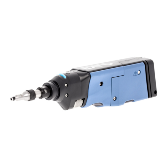
EXFO FIP-400B Series User Manual
Fiber inspection probe and connectormax2 mobile (android)
Hide thumbs
Also See for FIP-400B Series:
- User manual (103 pages) ,
- User manual (142 pages) ,
- User manual (111 pages)


Need help?
Do you have a question about the FIP-400B Series and is the answer not in the manual?
Questions and answers