
Related Manuals for DPS Telecom Building Status Unit II

Summary of Contents for DPS Telecom Building Status Unit II
- Page 1 Building Status Unit II User Manual Visit our website at www.dpstelecom.com for the latest PDF manual and FAQs. D-OC-UM04A.22100 October 22, 2004...
- Page 2 Notice The material in this manual is for information purposes and is subject to change without notice. DPS Telecom shall not be liable for errors contained herein or consequential damages in connection with the furnishing, performance, or use of this...
-
Page 3: Table Of Contents
Contents Visit our website at www.dpstelecom.com for the latest PDF manual and FAQs Introduction Features and Benefits Building Status Unit II Application Diagrams Shipping List Specifications Tools Needed Install the BSU II Hardware Mounting Wire for Communication 6.2.1 Connection to the NetGuardian 832A... -
Page 5: Introduction
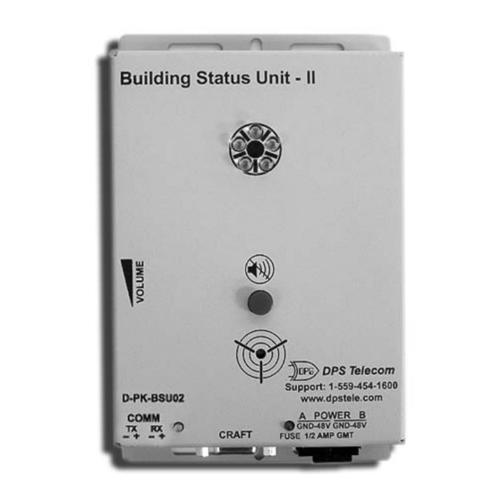
Fig. 1.1. The Building Status Unit II (BSU II). A companion product to the NetGuardian 832A, the Building Status Unit II (BSU II) provides local annunciation whenever an alarm occurs. The BSU II has a large visual indicator that will alert technicians to alarms. You may acknowledge alarms locally on the unit, which will in turn acknowledge the alarm in the NetGuardian as well. -
Page 6: Shipping List
Shipping List While unpacking the Building Status Unit II, please make sure that all of the following items are included. If some parts are missing, or if you ever need to order new parts, please refer to the part numbers listed and call DPS Telecom at (800) 622-3314. -
Page 7: Specifications
+32° to +140° F (0° to +60° C) Operating Humidity: 0% to 95% non-condensing Tools Needed To install the Building Status Unit II, you'll need the following: A small screw driver A medium size screw driver Install the BSU II Hardware Mounting Mount the BSU II in the desired location using the mounting screws provided. -
Page 8: Wire For Power
Pin # Signal Description DB9 RS-485 – + – + Transmit data + 1 2 3 4 Not connected Not connected Receive data + Not connected Transmit data - Not connected Not connected Receive data - Fig. 6.1 Communication lines between the NetGuardian and the BSU II. 4-Wire Pin No. -
Page 9: Configure The Bsu Ii
Configure the BSU II Setting Internal Address Each BSU II must have a separate internal address. The address is defined by how the DIP switches 1-4 are set on the unit. Refer to Figure 7.1 and Table 7.A and B for DIP switch definitions of the corresponding addresses. Note: The addressing begins at address 1 and increments in sequences up to address 12. -
Page 10: Setting The Com Port Baud Rate
Setting the COM Port Baud Rate Each BSU IIs baud rate must match the NetGuardian baud rate setting. The baud rate is defined by setting DIP switches 5-7 — see Figure 7.2 and Table 7.C for DIP switch baud rate definitions. Note: The required baud rate for NetGuardian interface is 1200. -
Page 11: Configure The Sound On Time Settings
In the GLD/BSU field enter 1 as the number of BSU IIs connected to the NetGuardian — see Figure 8.1. Click data port 8 — the default settings will appear. Select your BSU II baud rate from the Baud drop-down menu. You will not be able to change any of the other settings. -
Page 12: Using The Web Browser Interface
Fig. 8.3 Click the Write button to write any changes to the NetGuardian. Using the Web Browser Interface Use the following steps to provision the NetGuardian via the Web Browser Interface: From the main screen, select "Edit" then "Ports." 2. Scroll down to the Options portion of the Ports screen. 3. -
Page 13: Configure The Sound On Time Settings
Fig. 8.5 Select a different baud rate in the Edit > Ports > Data Ports screen. 8.2.1 Configure the Sound On Time Settings The Sound On Time defines how long the audible notification will sound and how long the LEDs will flash when there is a new alarm event. -
Page 14: Comm And Fuse Alarm Led Indications
Fig. 8.6 Define the amount of time the BSU II audible notification will sound in the Edit > Timers screen. COMM and Fuse Alarm LED Indications Color Action Description Flash Receive activity Green Flash Transmit activity COMM Communication failure Green Slow blink (communication link idle for more than 2 mins) -
Page 15: Audible Notification
Audible Notification The NetGuardian may activate the BSU II speaker as certain conditions occur. Press the large red ACO button to locally terminate the sound. You can also use the thumb wheel to adjust the speaker volume. Fig. 10.1 Press the large red ACO button to terminate the audible notification. Fig. -
Page 16: Audible And Led Alarm Notification Operation
flashing green for transmit and red for receive. 11.2 Audible and LED Alarm Notification Operation When a reportable event occurs, like an SNMP trap or an ASCII page, the speaker will sound and the LEDs will blink. The speaker and LEDs will auto-acknowledge in the time specified by Sound On Time in the NetGuardian. See Section 8 for more information on configuring the Sound On Time settings via NGEdit or the Web Browser. -
Page 17: Updating The Firmware
The Open Protocol button opens the Protocol Window. The Protocol Window is for troubleshooting purpose only. Do not open the Protocol Window unless you are requested to do so by DPS Telecom Technical Support Personnel. Note: Do not abort or disturb the upgrade process in any way while downloading is in progress as this may cause the unit to become inoperable. - Page 18 Please be at or near your equipment when you call DPS Telecom Technical Support. This will help us solve your problem more efficiently. 4. Call during Customer Support hours. Customer support hours are Monday through Friday, from 7 A.M. to 6 P.M., Pacific time. During these hours Technical Support representatives are on duty in our fully equipped simulation lab.
- Page 19 Warranty DPS Telecom warrants, to the original purchaser only, that its products a) substantially conform to DPS' published specifications and b) are substantially free from defects in material and workmanship. This warranty expires five years from the date of product delivery with respect to hardware and ninety days from the date of product delivery with respect to software.
- Page 20 “We protect your network like your business depends on it” www.dpstelecom.com 4955 E. Yale • Fresno, CA 93727 Support: (559) 454-1600 • Sales: (800) 622-3314 • Fax: (559) 454-1688...
Need help?
Do you have a question about the Building Status Unit II and is the answer not in the manual?
Questions and answers