Table of Contents
Advertisement
Quick Links
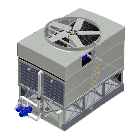
IDC2 Evaporative Condenser
THIS MANUAL CONTAINS RIGGING, ASSEMBLY, START-UP,
AND MAINTENANCE INSTRUCTIONS. READ THOROUGHLY
BEFORE BEGINNING INSTALLATION. FAILURE TO FOLLOW THESE
INSTRUCTIONS MAY RESULT IN PERSONAL INJURY OR DEATH,
DAMAGE TO THE UNIT, OR IMPROPER OPERATION.
Please check www.jci.com/frick for the latest version of this publication.
Form 140.940-IOM (DEC 2013)
INSTALLATION - OPERATION - MAINTENANCE
File:
SERVICE MANUAL - Section 140
Replaces:
140.940-IOM (FEB 2013)
Dist:
3, 3a, 3b, 3c
Advertisement
Table of Contents

Related Manuals for Johnson Controls Frick IDC2


Summary of Contents for Johnson Controls Frick IDC2
- Page 1 Form 140.940-IOM (DEC 2013) INSTALLATION - OPERATION - MAINTENANCE File: SERVICE MANUAL - Section 140 Replaces: 140.940-IOM (FEB 2013) Dist: 3, 3a, 3b, 3c IDC2 Evaporative Condenser THIS MANUAL CONTAINS RIGGING, ASSEMBLY, START-UP, AND MAINTENANCE INSTRUCTIONS. READ THOROUGHLY BEFORE BEGINNING INSTALLATION. FAILURE TO FOLLOW THESE INSTRUCTIONS MAY RESULT IN PERSONAL INJURY OR DEATH, DAMAGE TO THE UNIT, OR IMPROPER OPERATION.
-
Page 2: Table Of Contents
140.940-IOM DEC 13) IDC2 EVAPORATIVE CONDENSERS Page 2 INSTALLATION - OPERATION - MAINTENANCE CONTENTS INSTALLATION GENERAL MAINTENANCE INFORMATION ....10 INITIAL & SEASONAL START-UP ......11 RIGGING AND ASSEMBLY INSTRUCTIONS ....3 General ................11 Check Unit Before Rigging ............3 Cleaning ................11 Unit Weights.................3 Inspection ................ -
Page 3: Rigging And Assembly Instructions
IDC2 EVAPORATIVE CONDENSERS 140.940-IOM (DEC 13) Page 3 INSTALLATION INSTALLATION WARNING Operation, maintenance, and repair of this e quipment RIGGING AND ASSEMBLY INSTRUCTIONS should be undertaken only by personnel qualified to do so. Proper care, procedures and tools must be used in Check Unit Before Rigging handling, lifting, installing, operating, maintaining and When the unit is delivered to the jobsite, check it thoroughly to... -
Page 4: Section Assembly Of Two-Piece Cells
140.940-IOM (DEC 13) IDC2 EVAPORATIVE CONDENSERS Page 4 INSTALLATION SECTION ASSEMBLY OF TWO-PIECE CELLS NOTICE • Position the lower section on the supports and bolt in place. For weight information, refer to submittal drawing package. • Wipe moisture and dirt from the perimeter flange. NOTICE •... -
Page 5: Assembly Of Multi-Cell Units
IDC2 EVAPORATIVE CONDENSERS 140.940-IOM (DEC 13) Page 5 INSTALLATION Figure 3 - Lower Section Multi-piece Lift Figure 3a. Middle Section Lift Figure 3b. Mechanical Section Lift Figure 5a - Typical Bolting • Using drift pins in the bolt holes provided, as shown in Figure 5, guide the middle section onto the lower section. -
Page 6: Idc2 Flume Box Installation
140.940-IOM (DEC 13) IDC2 EVAPORATIVE CONDENSERS Page 6 INSTALLATION Refer to the certified unit print for the proper orientation of • Using drift pins to align the bolt holes, place the flume box each cell. The cell number and “face” are stenciled on the outer over the opening in the basin of Cell #1 and fasten into place. -
Page 7: Water Baffles
IDC2 EVAPORATIVE CONDENSERS 140.940-IOM (DEC 13) Page 7 INSTALLATION Lower Baffle Lower Baffle Side Side Baffle Baffle Figure 8a - Step 1 Figure 8b - Step 2 Figure 9a - External Motor Mount Assembly Instruction 3/8” Screw 3/8” 1/2" Washer Figure 8c - Step 3 1/2"... -
Page 8: Sloped Ladder Installation
140.940-IOM (DEC 13) IDC2 EVAPORATIVE CONDENSERS Page 8 INSTALLATION Installation of the Side Outlet Depressed Sump Box Sloped Ladder Installation To install the side outlet depressed sump box, follow these Remove ladder from cold water basin. Slide the ladder bracket steps: assembly (attached to side of ladder) into the ladder mounting guides located on the side of the condenser (Figure 12). -
Page 9: Operation
IDC2 EVAPORATIVE CONDENSERS 140.940-IOM (DEC 13) Page 9 OPERATION OPERATION WARNING The basin heater is not designed to prevent icing during WARNINGS unit operation. Do not perform any service on or near the fans, motors, and WARRANTIES drives, or inside the unit without first ensuring that the fans and pumps are disconnected, locked out, and tagged out. -
Page 10: General Maintenance Information
140.940-IOM (DEC 13) IDC2 EVAPORATIVE CONDENSERS Page 10 OPERATION • Air: The most harmful atmospheric conditions are those with CAUTION unusual quantities of industrial smoke, chemical fumes, salt or heavy dust. Such airborne impurities are carried into the Mechanical and operational methods must be employed equipment and absorbed by the recirculating water to form to protect these products against damage and/or reduced a corrosive solution. -
Page 11: Initial & Seasonal Start-Up
IDC2 EVAPORATIVE CONDENSERS 140.940-IOM (DEC 13) Page 11 OPERATION Start-up INITIAL & SEASONAL START-UP WARNING WARNING Check to ensure the controls for the fan motor are set to Do not perform any service on or near the fans, motors, and allow a maximum of six on-off cycles per hour to prevent drives, or inside the unit without first ensuring that the fans motor overload. -
Page 12: Extended Shutdown
140.940-IOM (DEC 13) IDC2 EVAPORATIVE CONDENSERS Page 12 OPERATION NOTICE After 24 hours of operation under thermal load, perform the following services: ü Check the unit for any unusual noise or vibrations. ü Check the operating water level in the cold water basins. ü... -
Page 13: Maintenance
- Check each blade in the area of the shank for any signs AllIDC2modelsexcept of cracking. If cracking is found, the fan motor should be 11¾” 9” IDC2-x-1218-x locked out immediately. Contact Johnson Controls-Frick IDC2-x-1218-x 13½” 10½” or your local Frick Factor for assistance. •... - Page 14 140.940-IOM (DEC 13) IDC2 EVAPORATIVE CONDENSERS Page 14 MAINTENANCE - The motor base assembly has been pre-aligned at the fac- tory. Mount the motor base assembly to the unit and verify alignment. Install the belt and follow the belt tensioning directions below.
-
Page 15: Fan Motors
IDC2 EVAPORATIVE CONDENSERS 140.940-IOM (DEC 13) Page 15 MAINTENANCE FAN MOTORS • Only ubricate the bearings with one of the following com- patible water resistant greases which are suitable for ambi- Model Specific Fan Drive System Descriptions ent temperatures ranging from - 65°F (-53.9°C) to +250°F Externally Mounted Motor (Models IDC2-x-7409-x and IDC2- (121.1°C). -
Page 16: Water Level Control
140.940-IOM (DEC 13) IDC2 EVAPORATIVE CONDENSERS Page 16 MAINTENANCE • Mechanical Makeup Valve Assembly Quarterly or more often as required, turn off the pump. Flush any dirt or debris from the water distribution system A float-operated mechanical water makeup assembly is fur- to prevent clogged nozzles. -
Page 17: Recommended Maintenance Services
IDC2 EVAPORATIVE CONDENSERS 140.940-IOM (DEC 13) Page 17 MAINTENANCE WARNING Do not perform any service on or near the fans, motors, and drives, or inside the unit without first ensuring that the fans and pumps are disconnected, locked out, and tagged out. RECOMMENDED MAINTENANCE SERVICES Type Service Start-Up... - Page 18 140.940-IOM (DEC 13) IDC2 EVAPORATIVE CONDENSERS Page 18 NOTES...
- Page 19 IDC2 EVAPORATIVE CONDENSERS 140.940-IOM (DEC 13) Page 19 NOTES...
- Page 20 Form 140.940-IOM (2013-12) JOHNSON CONTROLS Supersedes: 140.940-IOM (2013-02) 100 CV Avenue Subject to change without notice Waynesboro, PA 17268-1206 USA Published in USA • 01/15 PDF Phone: 717-762-2121 • FAX: 717-762-8624 www.jci.com/frick © 2015 Johnson Controls Inc. - ALL RIGHTS RESERVED...
Need help?
Do you have a question about the Frick IDC2 and is the answer not in the manual?
Questions and answers