Advertisement
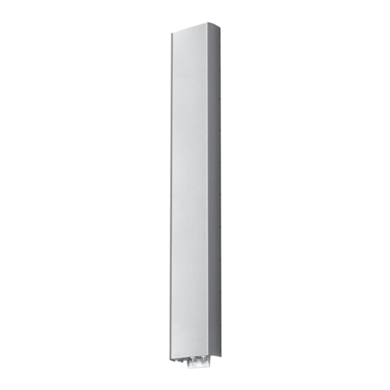
2-Port Antenna
Frequency Range
Dual Polarization
Half-power Beam Width
Integrated replaceable Remote Control Unit
Adjustable Electrical Downtilt
2-Port Antenna iRCU 698–894 65° 16dBi 0°–10°T
Type No.
A) Antenna specifi cations
Frequency range
Polarization
Gain
Horizontal Pattern:
Half-power beam width
Front-to-back ratio
Cross polar ratio
Maindirection
Sector
Vertical Pattern:
Half-power beam width
Electrical tilt
Min. sidelobe suppression for
fi rst sidelobe above main beam:
Average:
Impedance
VSWR
Isolation, between ports
Intermodulation IM3
Max. power per input
B) iRCU specifi cations (86010149)*
Field replaceable without dismantling the antenna
Logical interface ex factory
Protocols
Hardware interface
Power supply
Power consumption
Adjustment time (full range)
Adjustement cycles
Certifi cation
* See mounting instructions and warnings.
1)
The protocol of the logical interface can be switched from 3GPP/AISG 2.0 to AISG
1.1 and vice versa with a vendor specifi c command. Start-up operation of the iRCU
86010149 is possible in a RET system supporting AISG 1.1 or supporting 3GPP/AISG
2.0 after performing a layer 2 reset before address assignment. The protocol can also
be changed as follows: AISG 1.1 to 3GPP: Enter „3GPP" into the additional data fi led
„Installer's ID" and perform a layer 7 reset or a power reset. 3GPP to AISG 1.1: Enter
„AISG 1" into the additional data fi eld „Installer's ID" and perform a layer 2 reset or a
power reset. After switching the protocol any other information can be entered into the
„Installer's ID" fi eld.
2)
The tightning torque for fi xing the connector must be 0.5 – 1.0 Nm ('hand-tightened'). The
connector should be tightened by hand only or using the torque screwdriver (85010080)
as described in the connecting cable data sheet (86010007, ...)!
3)
Tested to comply with FCC Standards. This device complies with part 15 of the FCC
Rules. Operation is subject to the following two conditions: (1) This device may not cause
harmful interference, and (2) this device must accept any interference received, including
interference that may cause undesired operation.
Arrow.com.
Downloaded from
MHz
698 – 806
°
+45, –45
dBd
dBi
°
dB
Copolar:
Average:
0°
dB
Typically: > 25
±60°
> 11, Avg. 15
°
°
° T
0 ... 5 ... 10
dB
16 ... 17 ... 17
dB
16 ... 19 ... 20
Ω
dB
dBc
W
1)
3GPP/AISG 2.0
Compliant to AISG 1.1 and 3GPP/AISG 2.0
2)
2 x 8pin connector acc. IEC 60130-9;
according to AISG:
– iRCU in (male): Control / Daisy chain in
– iRCU out (female): Daisy chain out
10 ... 30 V
< 1 W (stand by)
< 8.5 W (motor activated)
> 50,000
CE,
All specifications are subject to change without notice.
The latest specifications are available at www.kathreinusa.com
Kathrein USA Greenway Plaza II, 2400 Lakeside Blvd., Suite 650, Richardson TX 75082
Phone: 214.238.8800
R1
R1
698– 894
X
65°
iRCU
0°–10°
80010735
V01
R1, connector 1–2
R1, connector 1–2
698–894
824 – 894
+45, –45
13.35
15.5
67
> 30
Copolar:
35
Average:
Typically: > 25
> 11, Avg. 15
11.3
0– 10, continuously adjustable
0 ... 5 ... 10
18 ... 17 ... 16
20 ... 20 ... 20
50
< 1.5
> 30
< –150 (2 x 43 dBm carrier)
500 (at 50 °C ambient temperature)
40 sec.
3)
Fax: 214.238.8801
Email: info@kathrein.com
13.85
16
65
> 30
35
10
iRCU
698–894
in
out
+45°
8pin
8pin
7-16
male
female
80010735
698–894
–45°
7-16
Page 1 of 2
V01
Advertisement
Table of Contents

Summary of Contents for Kathrein 80010735V01
- Page 1 All specifications are subject to change without notice. The latest specifications are available at www.kathreinusa.com 80010735 Page 1 of 2 Kathrein USA Greenway Plaza II, 2400 Lakeside Blvd., Suite 650, Richardson TX 75082 Phone: 214.238.8800 Fax: 214.238.8801 Email: info@kathrein.com Arrow.com.
- Page 2 Any previous data sheet issues have now become invalid. All specifications are subject to change without notice. Page 2 of 2 80010735 The latest specifications are available at www.kathreinusa.com Kathrein USA Greenway Plaza II, 2400 Lakeside Blvd., Suite 650, Richardson TX 75082 Phone: 214.238.8800 Fax: 214.238.8801 Email: info@kathrein.com Arrow.com.
- Page 3 49.5 (1.45˝) All specifications are subject to change without notice. The latest specifications are available at www.kathreinusa.com 86010149 Page 1 of 2 Kathrein USA Greenway Plaza II, 2400 Lakeside Blvd., Suite 650, Richardson TX 75082 Phone: 214.238.8800 Fax: 214.238.8801 Email: info@kathrein.com Arrow.com.
- Page 4 Any previous datasheet issues have now become invalid. All specifications are subject to change without notice. Page 2 of 2 86010149 The latest specifications are available at www.kathreinusa.com Kathrein USA Greenway Plaza II, 2400 Lakeside Blvd., Suite 650, Richardson TX 75082 Phone: 214.238.8800 Fax: 214.238.8801 Email: info@kathrein.com Arrow.com.
- Page 5 Any previous data sheet issues have now become invalid. All specifications are subject to change without notice. The latest specifications are available at www.kathreinusa.com 738546 Page 1 of 1 Kathrein USA Greenway Plaza II, 2400 Lakeside Blvd., Suite 650, Richardson TX 75082 Phone: 214.238.8800 Fax: 214.238.8801 Email: info@kathrein.com Arrow.com.
- Page 6 All specifications are subject to change without notice. Page 1 of 2 The latest specifications are available at www.kathreinusa.com Kathrein USA Greenway Plaza II, 2400 Lakeside Blvd., Suite 650, Richardson TX 75082 Phone: 214.238.8800 Fax: 214.238.8801 Email: info@kathrein.com Arrow.com.
- Page 7 Carefully place the connector and fix the nut using a torque-wrench (according to the manufacturers guidelines). All specifications are subject to change without notice. Page 2 of 2 The latest specifications are available at www.kathreinusa.com Kathrein USA Greenway Plaza II, 2400 Lakeside Blvd., Suite 650, Richardson TX 75082 Phone: 214.238.8800 Fax: 214.238.8801 Email: info@kathrein.com Arrow.com.


Need help?
Do you have a question about the 80010735V01 and is the answer not in the manual?
Questions and answers