Table of Contents
Advertisement
Quick Links
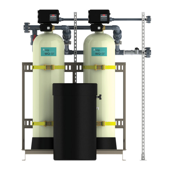
Installation, Operation and
Maintenance Manual
Lync WQ-SF
Complete Water Quality Solutions
Disclaimer
The information contained in this manual is subject to change without notice
from Lync, a division of Watts Water Technologies, Inc. Lync makes no
warranty of any kind with respect to this material, including, but not limited to,
implied warranties of merchantability and fitness for a particular application.
Lync is not liable for errors appearing in this manual, nor for incidental or
consequential damages occurring in connection with the furnishing,
performance, or use of these materials.
L- OMM-004_A
2/23/2022
•
Lync • 425 W Everman Pkway, St. 101 • Fort Worth, TX 76134
Technical Support • (800) 433-5654 (ext. 3) • Mon-Fri, 8 am - 5 pm CST
Engineered Solutions
USA: T: (817) 335-9531
© 2021 LYNC
Advertisement
Table of Contents

Related Manuals for Watts Lync WQ-SF


Summary of Contents for Watts Lync WQ-SF
- Page 1 Disclaimer The information contained in this manual is subject to change without notice from Lync, a division of Watts Water Technologies, Inc. Lync makes no warranty of any kind with respect to this material, including, but not limited to, implied warranties of merchantability and fitness for a particular application.
-
Page 2: Table Of Contents
TABLE OF CONTENTS Introduction ............................3 1.1. Principals of Softening and Ion Exchange ................. 4 1.2. Lync WQ-SF Skids Specifications: .................... 5 1.3. Feed Water Chemistry Requirements ..................6 1.4. General Skid Components ......................7 Installation and Operation ........................8 2.1. -
Page 3: Introduction
AND MAINTENANCE INSTRUCTIONS COULD RESULT IN PRODUCT FAILURE WHICH CAN CAUSE PROPERTY DAMAGE, PERSONAL INJURY AND/OR DEATH. Watts is not responsible for damages resulting from improper installation and/or maintenance. Local building or plumbing codes may require modifications to the information provided. You are required to consult the local building and plumbing codes prior to installation. -
Page 4: Principals Of Softening And Ion Exchange
Lync WQ-SF SECTION 2: Installation and Operation • The power outlet must be grounded. • For installations where plastic plumbing is used, install an appropriate grounding strap across the inlet and outlet piping of the building’s metal plumbing to ensure that a proper ground is maintained. -
Page 5: Lync Wq-Sf Skids Specifications
Step 5- Brine Tank Refill: Approximate Duration User Adjustable - In this final step of regeneration, water is added back into the brine tank so that a brine solution can be prepared for the next regeneration. Lync WQ-SF Skids Specifications: 1.2. Skid Model... -
Page 6: Feed Water Chemistry Requirements
Lync WQ-SF SECTION 2: Installation and Operation Backwash [GPM] Gravel [lbs/tank] Number of Brine Tank Brine Tank Size [in] 24 x 41 30 x 50 24 x 41 30 x 50 Salt Fill [lbs/tank] Electrical Data Voltage [V], Phase, Frequency [Hz] 120, 1Ø, 60... -
Page 7: General Skid Components
Lync WQ-SF SECTION 2: Installation and Operation General Skid Components 1.4. WQSF-025-N WQSF-050-N WQSF-075-N WQSF-100-N Figure 1-1: WQ-SF Skids Component Identification Technical Support • (800) 433-5654 • Mon-Fri, 8 am - 5 pm EST L- OMM-004_A • 2/23/2022 of 54... -
Page 8: Installation And Operation
Lync WQ-SF SECTION 2: Installation and Operation 2. Installation and Operation Pre-Installation Considerations 2.1. Unpack the crate(s) and pallets and make sure all components are accounted for according to the table below for each specific model. If any components are missing or damaged contact your Lync representative. - Page 9 If lubricant is required, a silicone compound is strongly recommended. Dow Corning ® Silicone Compound (available from Watts), is recommended for best possible results. Dow Corning ® 7 Release Compound is used in the manufacture of this control valve. The use of other types of lubricants may attack the control’s plastic or rubber components.
-
Page 10: Water Softener Skid Installation
Lync WQ-SF SECTION 2: Installation and Operation Water Softener Skid Installation 2.2. NOTES: For WQSF-075-N and WQSF-100-N systems, two skids require onsite connection to form a single water softener system with four tanks. The gasket kits are provided with the systems to connect the preassembled inlet, outlet, and drain piping headers of the two skids. - Page 11 Lync WQ-SF SECTION 2: Installation and Operation WQSF-025-N - WQSF-050-N WQSF-075-N - WQSF-100-N Figure 2-1: Unistrut Support for Piping Headers Technical Support • (800) 433-5654 • Mon-Fri, 8 am - 5 pm EST L- OMM-004_A • 2/23/2022 of 54...
-
Page 12: Mineral Tanks Resin Loading Procedure
Lync WQ-SF SECTION 2: Installation and Operation Mineral Tanks Resin Loading Procedure 2.3. After the mineral tank skid(s) has been placed in the final position, and will not need to be moved again, load the mineral tanks with gravel and resin media following the instructions below: 1. -
Page 13: Brine Tank Installation
Lync WQ-SF SECTION 2: Installation and Operation Brine Tank Installation 2.4. 2.4.1. Installation Location The brine tank(s) should set on a common elevation as the mineral tank and within distance so that it can be reached by the length of factory supplied brine tubing. If a smooth and level surface is not available, place brine tank(s) on a smooth piece of exterior plywood and level it by placing shims underneath the plywood. -
Page 14: Cables And Connections
Lync WQ-SF SECTION 2: Installation and Operation Figure 2-3: Brine Tank Overflow Port 2.4.3. Recommended Type of Salt Only purified salt should be used in the brining system. Palletized salt (“Button”, “Nugget”, and “Pellet”) or block salt (free binders) is recommended. Do not use granulated salt, as it will fall through the platform screen. - Page 15 Lync WQ-SF SECTION 2: Installation and Operation 2.5.2 Network/communication Cable Connections 1. Use the provided shielded CAT5 Network/Communication cable(s). 2. Connect each unit in series (do not form a loop) from one communication port to the next communication port. WQSF-025-N and WQSF-050-N...
- Page 16 Lync WQ-SF SECTION 2: Installation and Operation Wiring diagrams are reference only. All wiring should be done by a certified electrician and meet all electrical codes Figure 2-5: NXT2 Controller Cables and Connections Technical Support • (800) 433-5654 • Mon-Fri, 8 am - 5 pm EST L- OMM-004_A •...
-
Page 17: Operation
2815 2850 2900 (All Lync WQ-SF Skids) 3150 3900 • Regeneration Type Softener/Filter Meter Delayed Softener/Filter Meter Immediate (All Lync WQ-SF Skids) Time Clock Day of the Week Remote Regeneration • Regeneration Flow Downflow (All Lync WQ-SF Skids) Upflow Filter Features •... - Page 18 Lync WQ-SF SECTION 3: Operation distance • Full functional user interface with easy programming allowing forward and backwards menu navigation • Network two to eight valves via shielded CAT5 cables • LED Status Indicator Blue: In Service Flashing Blue: Regeneration Queued...
-
Page 19: Nxt2 Controller Display Features
Lync WQ-SF SECTION 3: Operation NXT2 Controller Display Features 3.2. Technical Support • (800) 433-5654 • Mon-Fri, 8 am - 5 pm EST L- OMM-004_A • 2/23/2022 of 54... -
Page 20: Nxt2 Controller Operation
Lync WQ-SF SECTION 3: Operation NXT2 Controller Operation 3.3. Setting the Time of Day NOTE: Set Time of Day on any unit and the rest of the units in the system will update the Time of Day automatically. Press and hold the Up button for 2 seconds. The "Time" value is displayed. Press the Up or Down buttons to adjust as desired. - Page 21 Lync WQ-SF SECTION 3: Operation Controller Operation During Regeneration In the Regeneration Cycle step display, the timer shows the current regeneration cycle name the valve is in, or has reached, and the time remaining in that step. Once all regeneration steps are complete, the timer returns to In Service and resumes normal operation.
- Page 22 Lync WQ-SF SECTION 3: Operation Remote Lock The controller does not allow the unit/system to go into Regeneration until the Regeneration Lockout Input signal to the unit is cleared. This requires a contact closure to activate the unit. The recommended gauge wire is 16 AWG with a maximum wire length run of 50 feet.
- Page 23 Lync WQ-SF SECTION 3: Operation Continuous Flow Detect Alert appears when specified continuous flow rate is detected during service over a specified duration. Continuous flow rate is adjustable from 0.1 to 999.9 GPM/LPM (accuracy of flow rate detected will vary based on capability of meter). Duration range is adjustable from 1 to 255 hours.
-
Page 24: Nxt2 Controller Systems Definition For Wq-Sf Skids
Lync WQ-SF SECTION 3: Operation Lock Window Lock Window prevents the unit from regenerating during a specified time frame. Two lock windows are available (Lock Window #1 and Lock Window #2). In Master Programming, enable a Lock Window then select the desired Lock Start time and Lock End time. - Page 25 Lync WQ-SF SECTION 3: Operation installed) will begin in Standby. At least one unit is In Service at all times. When flow rate to the Primary Service Unit increases to a user specified rate, the next unit in sequence will move from Standby to Service.
- Page 26 Lync WQ-SF SECTION 3: Operation 5. The third valves returns to stand by as demand decreases past the second trip point. 6. Valves return to stand by due to decreased total flow rate and trip points programmed. The valve with the most remaining volume will be the first to go into Standby.
-
Page 27: Start Up
Lync WQ-SF SECTION 3: Operation Start Up 3.5. 1. Ensure all meter and communication cables are properly installed and connected. 2. Ensure all inlet and outlet isolation valves and the bypass valves are in the closed position and the treated water faucet hot and cold side are in the open position. -
Page 28: User Mode Programming Flow Chart
Lync WQ-SF SECTION 3: Operation 18. Allow water to flow from the hot and cold side treated faucet until all air has been purged from the plumbing system. Then close both the hot and cold side treated water faucet. 19. Turn on water heaters. -
Page 29: Diagnostic Programming Mode Flow Chart
Lync WQ-SF SECTION 3: Operation • Press the Extra Cycle button to advance to the “Month” field. Press the Up or Down buttons to adjust as desired. • Press the Extra Cycle button to advance to the “Calendar Day” field. Press the Up or Down buttons to adjust as desired. - Page 30 Lync WQ-SF SECTION 3: Operation Example: Real-time flow rate reading Example: Peak flow since last regeneration Example: Gallons at the outlet since installation Example: Reserve Capacity setting Example: Gallons at the outlet since last regeneration Example: Time since last regeneration...
- Page 31 Lync WQ-SF SECTION 3: Operation Example: Record of error events chronologically Example: Average usage from past Sunday Example: Average usage from past 3 Sundays Example: Average usage from past Monday Example: Average usage from past 3 Mondays Example: Average usage from last Tuesday...
-
Page 32: Master Programming Mode Flow Chart
Lync WQ-SF SECTION 3: Operation Master Programming Mode Flow Chart 3.9. • Press and hold the Left and Down buttons simultaneously for 3 seconds to enter Master Programming mode. • To navigate, press the Extra Cycle button to advance to the next value. Press the Left button to retreat to the previous value. - Page 33 Lync WQ-SF SECTION 3: Operation Example: Range: 1-90 seconds Example: Range: 60-300 seconds Example: 2510, 2750, 2815, 2900, 3150, 3900 Example: Upflow Downflow Filter Example: Softener Meter Delayed Softener Meter Immediate Time Clock Day of the Week Example: Metric US...
- Page 34 Lync WQ-SF SECTION 3: Operation Example: Range: 0 - 240 M Example: Range: 0 - 240 M Example: Range: 0 - 240 M Example: Paddle (0.75", 1", 1.5", 2", 3") Turbine (0.75", 1.25", 1.5") Generic Example: Range: 0.1 to 999.9 gpm/Lpm...
-
Page 35: Wq-Sf Skids Factory Master Programming Settings Guide
Lync WQ-SF SECTION 3: Operation WQ-SF Skids Factory Master Programming Settings Guide 3.10. WQSF WQSF WQSF WQSF STEP RANGE -025-N -050-N -075-N -100-N SETTINGS On-Off REVIEW English, Francais, Deutsch, Italiano, Espanol, LANGUAGE ENGLISH Nederlands, Portugues ASSISTANCE Defined by Operator NAME 1... - Page 36 Lync WQ-SF SECTION 3: Operation OVERRIDE/TIME Off - 99 Days DRIVEN REGEN. TIME Any Time 02:00AM LOCK WINDOW #1 Off, On LOCK WINDOW #2 Off, On BACKWASH 0-240 Mins 10 Minutes DRAW 0-240 Mins 60 Minutes RAPID RINSE 0-240 Mins...
-
Page 37: Water Softener Down-Flow Brining Diagram
Lync WQ-SF SECTION 3: Operation Water Softener Down-Flow Brining Diagram 3.11. 1 - Service Position: Hard water enters unit from the valve inlet and flows down through the minerals. The softened water enters the center tube from the bottom distributor and flows up. It flows around the piston and exits the system from the valve outlet. - Page 38 Lync WQ-SF SECTION 3: Operation 2 – Backwash Position: Hard water enters the unit from the valve inlet and flows through the regenerating valve. It flows down the center tube and flows up the tank through the minerals. The water flows around the piston and goes to the drain line.
- Page 39 Lync WQ-SF SECTION 3: Operation 3- Brine Position: Hard water enters the unit from the valve inlet and flows up into the injector housing and down through the nozzle and orifice to draw brine from the brine tank. Brine solution flows down through the minerals and enters the center tube from the bottom distributor and flows up through the center tube.
- Page 40 Lync WQ-SF SECTION 3: Operation 4- Slow Rinse Position: Hard water enters the unit from the valve inlet, flows up into injector housing and down through the nozzle and orifice. Hard water flows around the piston and flows down through the minerals and from there, it flows up from the center tube. Water flows around the piston and leaves the unit through the drain line.
- Page 41 Lync WQ-SF SECTION 3: Operation 5- Rapid Rinse Position: Hard water enters from the valve inlet and flows thru the regenerating valve. It directly flows down through the minerals and flows up from the center tube. The water flows around the piston and leaves the unit from the drain line.
- Page 42 Lync WQ-SF SECTION 3: Operation 6- Brine Tank Fill Position: Hard water enters from the valve inlet and flows through the service valve. Hard water flows down through the minerals and after getting conditioned, it enters the bottom distributor and flows up the center tube. The soft water flows around the piston and leaves the system through the valve outlet.
-
Page 43: Maintenance
Lync WQ-SF SECTION 5: MAINTENANCE 4. Maintenance Replacing the Ion Exchange Resin 4.1. NOTE: Ion exchange resin may need to be replaced periodically due to physical breakdown caused by chlorine/chloramine disinfectants, or fouling caused by certain metals such as iron and manganese. -
Page 44: System Troubleshooting
Lync WQ-SF SECTION 5: MAINTENANCE 15. If replacing gravel, inspect lower distributor screens for damage and replace if necessary. 16. To add new media and reconnect control valve to mineral tank follow the instructions in section 2.3.. 17. Reconnect inlet, outlet, and drain piping headers to the control valves and tighten the plumbing union fittings on each of these plumbing lines. - Page 45 Lync WQ-SF SECTION 5: MAINTENANCE system operation. Or, if more than one unit has been queued for regeneration, then the queue is rebuilt according to which one communicates first. Message Displayed Causes for Error Correction Number of NXT2 detected does...
- Page 46 Lync WQ-SF SECTION 5: MAINTENANCE Make sure distributor tube is not Leak at distributor tube cracked. Check O-Ring and tube pilot Replace seals and spacers and/or Internal valve leak piston Check salt dosage requirements and Reserve capacity has been exceeded...
-
Page 47: Replacement Parts
Lync WQ-SF SECTION 5: MAINTENANCE General Service Hints For Meter Control: Problem: Softener delivers hard water. Cause could be: Reserve capacity has been exceeded. Correction: Check salt dosage requirements and reset program wheel to provide additional reserve. Cause could be: Meter is not measuring flow. - Page 48 Fiberglass Mineral Tank 21" x 62"- Almond 68100694 Color - 4" Top Opening with Black Base 68100326 Resin - Watts Brand 8% crosslink - 1CF/Bag Gravel 1/8"x1/16" (#20) red marking – 68100354 50lbs/Bag Brine Tank 24”X41” Black – Shell Only 68102494 Brine Tank 30”X50”...
- Page 49 Lync WQ-SF SECTION 5: MAINTENANCE 4.3.2 2900 Upper Powerhead Item Part No. Description 68104633 2900 Upper Powerhead NXT2 Technical Support • (800) 433-5654 • Mon-Fri, 8 am - 5 pm EST L- OMM-004_A • 2/23/2022 of 54...
- Page 50 Lync WQ-SF SECTION 5: MAINTENANCE 4.3.3 2900 Lower Powerhead Item Part No. Description 68104635 2900 Lower Powerhead Technical Support • (800) 433-5654 • Mon-Fri, 8 am - 5 pm EST L- OMM-004_A • 2/23/2022 of 54...
- Page 51 Lync WQ-SF SECTION 5: MAINTENANCE 4.3.4 NXT2 Controller Item Part No. Description 68104777 Timer Assembly. NXT2 Technical Support • (800) 433-5654 • Mon-Fri, 8 am - 5 pm EST L- OMM-004_A • 2/23/2022 of 54...
- Page 52 Lync WQ-SF SECTION 5: MAINTENANCE 4.3.5 Fleck 2900 Valve Body Item Part No. Description 68104729 Part FL Seal and Spacer Kit, 2900S, Upper 68104731 Piston Assembly, 2900S, Downflow, Upper 68104556 Part Seal & Spacer Kit 2900 Lower 68104733 Part Piston Assembly 2900S, Downflow, NHWBP, Lower...
- Page 53 Lync WQ-SF SECTION 5: MAINTENANCE 4.3.6 Fleck 1710 Brine Valve and Injector Item Part No. Description 68104658 1710 Brine VLV F/2750 2900 PLST W/ 2.0 GPM Technical Support • (800) 433-5654 • Mon-Fri, 8 am - 5 pm EST L- OMM-004_A •...
- Page 54 Lync WQ-SF SECTION 5: MAINTENANCE 4.3.7 2” Flow Meter Item Part No. Description 68104756 Meter Assembly 2.0 SST MECH/ELEC CA Technical Support • (800) 433-5654 • Mon-Fri, 8 am - 5 pm EST L- OMM-004_A • 2/23/2022 of 54...
Need help?
Do you have a question about the Lync WQ-SF and is the answer not in the manual?
Questions and answers