
Subscribe to Our Youtube Channel
Related Manuals for 3Com 3C16476CS


Summary of Contents for 3Com 3C16476CS
- Page 1 Baseline Switch 2250 Plus User Guide Installationsanleitung 3C16476CS http://www.3com.com/ Part No. 10015237 Rev. AA Published August 2006...
- Page 2 3Com Corporation • 350 Campus Drive • Marlborough • MA USA 01752-3064 Copyright © 2006, 3Com Corporation. All rights reserved. No part of this documentation may be reproduced in any form or by any means or used to make any derivative work (such as translation, transformation, or adaptation) without written permission from 3Com Corporation.
-
Page 3: Table Of Contents
ONTENTS BOUT UIDE Conventions Related Documentation Documentation Comments NTRODUCING THE ASELINE Overview of the Baseline Switch 2250 Plus Features and Capabilities Autosensing of MDI/MDIX Connections Autonegotiating 10/100 Mbps Ports SFP Ports Traffic Prioritization Forwarding of BPDU Packets Physical Features Front Panel... - Page 4 Backup Configuration Restore Configuration Firmware Upgrade Initialize Reboot System Access System Time SNMP Configuring VLANs VLAN Forwarding Tagged/Untagged Frames Sample VLAN Configurations Spanning Tree IGMP Snooping IGMP Query Broadcast Storm Configuring Port Settings Administration Speed/Duplex for 1000 Mbps Connections Link Aggregation Spanning Tree per Port Port Mirroring QoS VoIP Traffic Settings...
-
Page 5: About This Guide
BOUT UIDE This guide describes how to install your Switch and perform initial management configurations. This guide is intended for use by network administa- tors who are responsible for installing and setting up network equipment. Consequently, it assumes a basic working knowledge of LANs (local area networks). -
Page 6: Related Documentation
BOUT UIDE Related Documentation In addition to this guide, each 3Com Baseline Switch 2250 Plus documentation set includes the following: Online Help – Accessible from the Web interface, ■ provides information that helps you perform tasks using the Web interface. -
Page 7: Introducing The Baseline Switch
This chapter provides an overview of the features and ® capabilities of the 3Com Baseline Switch 2250 Plus. It also identifies the contents of the Switch package and helps you get to know the physical features of the device. Overview of the Baseline Switch 2250 Plus The 3Com®... -
Page 8: Sfp Ports
Traffic prioritization uses the multiple traffic queues that are present in the hardware of the Switch to ensure that high priority traffic is forwarded on a different queue from lower priority traffic, and is given preference over that traffic. -
Page 9: Physical Features
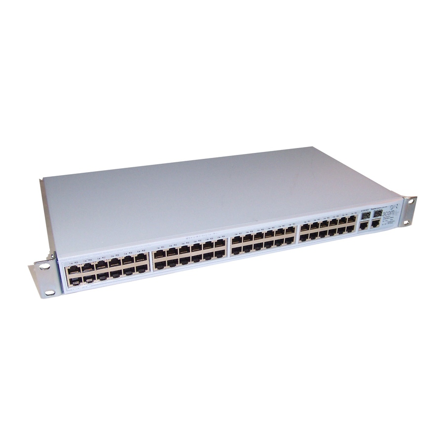
Panel” page Figure 1 Front and Rear Panels Front Panel The front panel of the Switch contains a series of indi- cator lights (LEDs) that help describe the state of vari- ous networking and connection operations. (1) 48 RJ-45 Ports WARNING: RJ-45 Ports. - Page 10 Switch and remote 1000 Mbps workgroups or to create a high-capacity aggregated link backbone connection. SFP ports are numbered 49 and 50 on the Switch. When an SFP port is active, it has priority over the 10/100/1000 port of the same number. The corresponding 10/100/1000 port is disabled when an SFP transceiver is plugged in.
- Page 11 Status Meaning Flashing Yellow Packets are being received or transmitted on the port at 10 Mbps Link not established, either nothing is connected to the port, or there is a problem. Verify that the attached device is ■ powered on Verify that the cable or fiber is the ■...
-
Page 12: Rear Panel
1: I HAPTER NTRODUCING THE ASELINE (5) Power LED The Power LED shows the power status of the Switch. Table 7 Power LED Status Meaning Green The unit is powered on and ready for use Flashing Power-on self-test is in progress... -
Page 13: Installing The Switch
NSTALLING THE This chapter contains information that you need to install and set up the Switch. It covers the following topics: Positioning the Switch ■ Rack-Mounting or Free-Standing ■ Supplying Power to the Switch ■ Connecting a Network Device ■... -
Page 14: Aufstellen Des Switch
When mounting the unit, take note of the guidelines given in “Positioning the Switch” page The Switch is 1U (1.75 in.) high and will fit in a stan- dard 19-inch rack. CAUTION: Before continuing, disconnect all cables from the unit. Remove the self-adhesive pads from the underside of unit, if already fitted. -
Page 15: Montagesatz Anweisungen
Baugruppenträger benutzt. Bei der Montage der Baugruppe beachten Sie die Anweisungen aus “Aufstellen des Switch“. Der Switch ist eine Baueinheit hoch und passt in einen Standard 19'' (Zoll) Baugruppenträger. ACHTUNG: Entfernen Sie alle Kabel, bevor Sie fort- fahren. Entfernen Sie die selbstklebenden Polster (Füße) von der Unterseite der Baugruppe, falls diese... -
Page 16: Placing Units On Top Of Each Other
Baseline and SuperStack units, the smaller units must be positioned at the top. If you are placing Switch units one on top of the other, you must use the self-adhesive rubber pads supplied. Apply the pads to the underside of each Switch, sticking one in the marked area at each cor- ner. -
Page 17: Connecting A Network Device
If the Switch still does not operate, con- ■ tact your 3Com network supplier If POST fails, try the following: Power off the Switch, and then power it on again. ■ Check the Power LED and see if POST was successfully completed. -
Page 18: Using Sfp Transceivers
SFP transceiver from an SFP slot. SFP transceivers are hot-insertable and hot-swappa- ble. You can remove them from and insert them into any SFP port without having to power off the Switch. Approved SFP Transceivers The following list of approved SFP transceivers is cor-... -
Page 19: Removing An Sfp Transceiver
Performing Spot Checks Performing Spot Checks At frequent intervals, you should visually check the Switch. Regular checks can give you an early warning of a possible failure; any problems can then be attended to when there will be least effect on users. - Page 20 2: I HAPTER NSTALLING THE WITCH...
-
Page 21: Interface
IP address that is assigned to the Switch, and configure its advanced settings. If you only want the Switch to function as a basic layer 2 switch, you do not need to access the Web interface and configure the Switch. - Page 22 NTERFACE Figure 6 Discovered Devices Screen On the Discovered Devices screen, click Baseline Switch 2250 Plus, and then click Next. The Completing the 3Com Discovery Application screen appears. Click Finish. The logon dialog box for the Web interface appears.
-
Page 23: Logging On To The Web Interface
Navigating the Web Interface The Web interface has been designed to enable you to easily perform advanced configuration tasks and view information about the Switch. Menu The menu is located on the left side of the Web interface. When you click an item on the menu, the related screen appears in the main part of the interface. - Page 24 Manages the device. IP Setup Allows you to setup, modify, or view the IP configuration parameters. Backup Configuration Allows you to backup the Switch’s configuration. Restore Configuration Allows you to restore a saved configuration. Firmware Upgrade Allows you to upgrade the current firmware via HTTP.
-
Page 25: Buttons
■ Display 802.1X detailed information per ■ port. Configure 802.1X settings. ■ Monitoring Display Switch monitoring information. Address Table Displays MAC address table information for ports and VLANs. Cable Diagnostics Contains tabs that allow you to: Display selected cable diagnostics ■... -
Page 26: Accessing The Interface Without Using Discovery
NTERFACE Manually Assigned (Static) IP Address If you assigned a static IP address to the Switch, you need to use that IP address to access the Web interface the next time you want to configure the Switch. -
Page 27: Onfiguring The
■ Monitoring ■ Configuration Overview The Switch is shipped ready for use. If you only want the Switch to function as a basic layer 2 switch, you do not need to access the Web interface and configure the Switch. You only need to access the Web interface if you... -
Page 28: Polling Interval
Support, you may be asked to print out the information on this screen. Polling Interval Enter the interval in seconds you would like the Switch to refresh. (Range: 10 to 180 seconds; 0 to disable polling). Figure 10 Device View To set the polling interval: Click the Device Summary menu, click Polling Interval tab. -
Page 29: Administration Settings
Modifying the IP Address Settings To enable devices on the network to communicate with the Switch, you need to assign an IP address to it — either by DHCP or by assigning a static IP address. By default, the Switch performs automatic IP configuration and assigns an IP address to itself. -
Page 30: Ip Setup
4: C HAPTER ONFIGURING THE IP Setup To set the IP address for the Switch: Click Administration, then IP Setting on the menu. The IP Settings screen appears. Follow the IP Setup Wizard to complete the setup. This wizard can also be used to set system name, location and contact information. -
Page 31: Firmware Upgrade
Web browser to *.* to be able to see the file. The file will be copied to the Switch, and once this has completed, the Switch will restart. Although the upgrade process has been designed to preserve your... -
Page 32: Reboot
Clicking on Administration, then Reboot on the menu has the same effect as power cycling the unit. No configuration information will be lost. Reboot the Switch if you are experiencing problems and you want to re-establish your Internet connection. Any network users that are currently accessing the... -
Page 33: Modify User
This page allows you to modify a user’s access level and password. Administration Settings Figure 18 Modify User Screen Remove User To remove a user from the Switch, click on the user name, then click Remove. Figure 19 Remove User Screen... -
Page 34: System Time
4: C HAPTER ONFIGURING THE System Time Click Administration, then System Time on the menu. This screen allows you to set the system time. You can set the Year, Month, Day, Hours, Minutes, and Seconds. Figure 20 System Time Screen SNMP Simple Network Management Protocol (SNMP) is a communication protocol designed specifically for... -
Page 35: Configuring Vlans
LAN. You can use the Switch to create VLANs to organize any group of ports into separate broadcast domains. VLANs confine broadcast traffic to the originating group and help eliminate broadcast storms in large networks. -
Page 36: Vlan
■ VLAN Detail ■ Setup Use the Setup screen to create VLANs on the Switch. To propagate information about VLAN groups used on this Switch to external devices, you must specify a VLAN ID for each VLAN. Figure 25 Setup Screen... - Page 37 Figure 26 Modify VLAN Screen Enter a set of VLANs or select all VLANs to configure, then click Select. From the drop down menu, select a VLAN to modify. Select a membership use. Available options for each port include (only one option can be associated with a single port): Tagged ■...
- Page 38 4: C HAPTER ONFIGURING THE WITCH Rename Use the Rename screen to change the name of a VLAN. Figure 28 Rename Screen Enter a set of VLANs or select all VLANs to add to the rename list, then click Select. From the list of selected VLANs, choose a VLAN to rename.
-
Page 39: Forwarding Tagged/Untagged Frames
Configuring VLANs Figure 31 VLAN Detail Screen Forwarding Tagged/Untagged Frames Each port on the Switch is capable of passing tagged or untagged frames. The following describes how the Switch will handle tagged and untagged frames. -
Page 40: Sample Vlan Configurations
4: C HAPTER ONFIGURING THE The Switch will only forward a frame to ports that are members (tagged or untagged) of the VLAN to which the frame is assigned. If the port is an untagged member, the egress frame will be stripped of the VLAN tag and forwarded as untagged. -
Page 41: Spanning Tree
Create VLAN2 on both Switch 1 and Switch 2. You need not create VLAN1 since it exists by default. On Switch 1, set the ports that you want to be part of VLAN2 to Untagged. Set one port (for example, port 16) to Tagged. -
Page 42: Igmp Snooping
It then propagates the service request up to any neighboring multicast switch/router to ensure that it will continue WITCH IGMP Query to receive the multicast service. This procedure is called multicast filtering. -
Page 43: Broadcast Storm
Broadcast Storm Use the Broadcast Storm page to set the Switch’s broadcast storm control and threshold limits. A broadcast storm is an incorrect packet sent out on a network that causes most hosts to respond all at once, typically with wrong answers that start the process over again. - Page 44 ■ Flow Control – Enables and disables flow control ■ for the entire Switch. When flow control is enabled, the Switch regulates the packet flow so that a sending device does not transmit more packets than a receiving device can process. If flow control is disabled, packets may be dropped under certain periods of high traffic.
-
Page 45: Speed/Duplex For 1000 Mbps Connections
If connecting link partners are left to autonegotiate for a link manually set on this switch to full-duplex, they will always negotiate to half-duplex, resulting in a duplex mismatch. This can result in a significant reduction in network performance. - Page 46 4: C HAPTER ONFIGURING THE WITCH Guidelines for Creating Trunks Any port on the Switch can be used for creating a ■ trunk. This switch supports a maximum of four trunks. ■ Each trunk may contain up to four members.
-
Page 47: Spanning Tree Per Port
Click Remove. Spanning Tree per Port This administrative tool supports the configuration of the Switch to forward, or block and discard 802.1D spanning tree BPDU packets. Spanning tree is a bridge-based system for providing fault tolerance on networks and can be used to detect and disable network loops. - Page 48 4: C HAPTER ONFIGURING THE WITCH the Root Bridge generates BPDUs (Bridge Protocol Data Units) on all ports at a regular interval known as the Hello Time. All other spanning tree-compliant devices on the network have a designated Root Port. This is the Port nearest the Root Bridge and it is used for receiving the BPDUs initiated by the Root Bridge.
-
Page 49: Port Mirroring
Figure 47 Spanning Tree Setup Screen Port Mirroring The Switch allows you to monitor traffic going in and out of a particular port. For traffic monitoring to work, you need to attach a network analyzer to one port and use it to monitor the traffic of other ports in the stack. -
Page 50: Qos Voip Traffic Settings
4: C HAPTER ONFIGURING THE WITCH Figure 48 Port Mirroring Screen To set up port mirroring: Connect a network analyzer to a port. Access the Web interface. Click Port, then Port Mirroring on the menu. The Port Monitoring Setup Screen appears. Select the port number under Monitor Port to which you want to monitor. - Page 51 Use the Setup tab to configure the global settings for Voice VLAN. The following options are available: Voice VLAN Status – Enable or disable Voice VLAN ■ for the switch. Voice VLAN ID – Input the Voice VLAN ID for the ■ switch.
- Page 52 4: C HAPTER ONFIGURING THE WITCH Figure 52 QoS Port Detail Screen OUI Summary Use the OUI Summary tab to display the list of Organizational Unique Identifier for a company and their description. Figure 53 QoS OUI Summary Screen OUI Modify Use the OUI Modify tab to add to the list of Organizational Unique Identifier.
-
Page 53: Security
RADIUS-aware devices on the network. An authentication server contains a database of multiple user name/password pairs with associated privilege levels for each user or group that require management access to a switch. The RADIUS Client menu includes two tabs: Detail ■... -
Page 54: 802.1X Settings
4: C HAPTER ONFIGURING THE Figure 56 RADIUS Client Configure Screen 802.1X Settings The IEEE 802.1X (dot1x) standard defines a port-based access control procedure that prevents unauthorized access to a network by requiring users to first submit credentials for authentication. The 802.1X settings menu includes three tabs: Summary ■... - Page 55 (Range: 1-65535 seconds; Default: 3600 seconds) Quiet Period – Sets the time that a switch port ■ waits after the Max Request Count has been exceeded before attempting to acquire a new client.
-
Page 56: Monitoring
VLAN, or entering in a MAC Address, then click Select. Figure 60 Address Table Screen WITCH Cable Diagnostics The Switch provides cable diagnostic, which helps you detect and resolve issues with the attached cables. The Cable Diagnostics menu includes two tabs: Summary ■... - Page 57 Monitoring Diagnostics Use the Diagnostics tab to display individual port information on Test Result, Cable Fault Distance, and Last Update. Figure 62 Cable Diagnostic Screen...
- Page 58 4: C HAPTER ONFIGURING THE WITCH...
-
Page 59: Troubleshooting
“Automatic IP Configuration” page 29 for more information. If you forget the password to the Web interface after you set it, you will need to reset the Switch to regain access. See “Resetting to Factory Defaults” page 59 for instructions. -
Page 60: Forgotten Static Ip Address
Forgotten Static IP Address If you forget the static IP address that you assigned to the Switch and you need to access the Web interface, use the Discovery application to automatically detect the IP address and connect to the interface. -
Page 61: If The Problem Persists
Ensure that the connected device has either: Autonegotiation enabled, or ■ The ports are configured for half-duplex operation ■ All ports appear to show continual activity. There may be broadcast storms on the network. Remove port connections one at a time, waiting a few seconds between each port. - Page 62 5: T HAPTER ROUBLESHOOTING...
-
Page 63: Upport For Your Product
BTAINING Register Your Product Warranty and other service benefits start from the date of purchase, so it is important to register your product quickly to ensure you get full use of the warranty and other service benefits available to you. Warranty and other service benefits are enabled through product registration. -
Page 64: Appendix A: Obtaining Support For Your Product
A: O PPENDIX BTAINING UPPORT FOR http://eSupport.3com.com/ Product Support heading at http://www.3com.com/ Software Upgrades are the software releases that follow the software version included with your origi- nal product. In order to access upgrades and related documentation you must first purchase a service con- tract from 3Com or your reseller. - Page 65 Country Telephone Number Asia, Pacific Rim Telephone Technical Support and Repair Australia 1 800 678 515 Hong Kong 800 933 486 India +61 2 9424 5179 or 000800 6501111 Indonesia 001 803 61 009 Japan 00531 616 439 or 03 3507 5984 Malaysia 1800 801 777 New Zealand...
- Page 66 A: O PPENDIX BTAINING UPPORT FOR Country Telephone Number Antigua 1 800 988 2112 Argentina 0 810 444 3COM Aruba 1 800 998 2112 Bahamas 1 800 998 2112 Barbados 1 800 998 2112 Belize 52 5 201 0010 Bermuda 1 800 998 2112 Bonaire 1 800 998 2112...
-
Page 67: B Safety Information
3Com Switch Family Safety and Regulatory Informa- tion manual included with this product. NFORMATION You can find the 3Com Switch Family Safety and Regulatory Information manual on the product CD-ROM that was included with your switch. You can also download the safety manual from the 3Com... -
Page 68: Appendix B: Safety Information
B: S PPENDIX AFETY NFORMATION... -
Page 69: Related Standards
ECHNICAL Related Standards The 3Com Baseline Switch 2250 Plus has been designed to the following standards: Functional ISO 8802-3, IEEE 802.3 (Ethernet), IEEE 802.3u (Fast Ethernet), IEEE 802.3ab (Gigabit Ethernet), IEEE 802.3x (Flow Control), IEEE 802.1D (Bridging) MAC Address 4096 Safety UL/CUL (UL60950-1, CSA22.2 No... -
Page 70: Appendix C: Technical Information
C: T PPENDIX ECHNICAL NFORMATION... -
Page 71: Glossary
LOSSARY 10BASE-T The IEEE specification for 10 Mbps Ethernet over Category 3, 4 or 5 twisted pair cable. 100BASE-TX The IEEE specification for 100 Mbps Fast Ethernet over Category 5 twisted-pair cable. 1000BASE-LX IEEE 802.3z specification for Gigabit Ethernet over 9/125 micron core single-mode fiber cable. - Page 72 LOSSARY category 5e cables One of five grades of Twisted Pair (TP) cabling defined by the EIA/TIA-568 standard. Category 5e can be used in Ethernet (10BASE-T), Fast Ethernet (100BASE-TX) and Gigabit Ethernet (1000BASE-T) networks, and can transmit data at speeds of up to 1000 Mbps.
- Page 73 standard way for VLANs to communicate across switched networks. IEEE 802.1p An IEEE standard for providing quality of service (QoS) in Ethernet networks. The standard uses packet tags that define up to eight traffic classes and allows switches to transmit packets based on the tagged priority value.
- Page 74 InterNIC). subnet A network that is a component of a larger network. switch A device that interconnects several LANs to form a single logical LAN that comprises of several LAN segments. Switches are similar to bridges, in that they connect LANs of a different type;...
- Page 75 Enables the monitoring of port traffic by attaching a network analyzer to one switch port, in order to monitor the traffic of other ports on the Switch. trunking A method which specifies how to create a single high-speed logical link that combines several lower-speed physical links.
- Page 76 LOSSARY...
-
Page 77: Index
NDEX Numbers 1000BASE-LX 71 1000BASE-SX 71 1000BASE-T 71 100BASE-TX 71 10BASE-T 71 auto IP configuration 29 default IP address 29 default mask 29 autonegotiation 7 autosensing 7 bandwidth 71 client 72 configuration overview 27 connecting network device 17 SFP transceivers 18 conventions notice icons, About This Guide 5 text, About This Guide 5... - Page 78 SFP ports 8, 10 SFP transceivers 18 approved (supported) 18 inserting 18 removing 19 spot checks 19 subnet mask 74 switch defined 74 TCP/IP 73 defined 74 traffic 75 monitoring 49 troubleshooting 59 forgotten IP address 59 forgotten password 59...
-
Page 79: Regulatory Notices
EGULATORY OTICES FCC S TATEMENT This equipment has been tested and found to comply with the limits for a Class A digital device, pursuant to part 15 of the FCC rules. These limits are designed to provide reasonable protection against harmful interference when the equipment is operated in a commercial environment.
Need help?
Do you have a question about the 3C16476CS and is the answer not in the manual?
Questions and answers