Table of Contents
Advertisement
Quick Links
Advertisement
Table of Contents

Related Manuals for Chattanooga Group MOVEO XP


Summary of Contents for Chattanooga Group MOVEO XP
-
Page 2: Table Of Contents
Mōveo™ XP TABLE OF CONTENTS FOREWORD ..........1 5.6 S-2 LIMIT SWITCH REMOVAL AND REPLACEMENT ... .. 31 1- SAFETY PRECAUTIONS .. -
Page 4: Foreword
This table is to be used only under the supervision of a licensed practitioner. ©2007 Chattanooga Group or its affiliates, Hixson, Tennessee, USA. Any use of editorial, pictorial, or layout composition of this publication without express written consent from Chattanooga Group is strictly prohibited. This publication was written, illustrated, and prepared for print by Chattanooga Group. -
Page 5: 1- Safety Precautions
Mōveo™ XP 1- SAFETY PRECAUTIONS Explosion Hazard 1.1 PRECAUTIONARY INSTRUCTIONS The precautionary instructions found in this ext with an “Explosion Hazard” indicator section and throughout this manual are indicated will explain possible safety infractions if this by specific symbols. Understand these symbols equipment is used in the presence of flammable and their definitions before operating this anesthetics. - Page 6 Back Rest in the horizontal position. The table circuit from that which the other device(s) are should be left in the horizontal position (down) connected, and consult the Chattanooga Group when not in use. Service Department for help. •...
- Page 7 DEVICE. NEVER TRANSPORT THE PATIENT ON THE table. Do not use accessories manufactured by other TABLE. companies on this table. Chattanooga Group is not responsible for any consequence resulting from using • Make certain that the table is electrically grounded products manufactured by other companies.
- Page 8 Voltage Rating and Serial Number serious personal injury. Plate. Contact your Chattanooga Group • Do not move or elevate any cushion section dealer if the unit is not properly rated.
- Page 9 Mōveo™ XP 1- SAFETY PRECAUTIONS 1.1 PRECAUTIONARY INSTRUCTIONS (CONTINUED) Correct • DO NOT adjust the angles of the Foot Plates while the patient has any weight resting on them. • Both Mechloks® on the Foot Plates should always be kept at an angle. When adjusting the Foot Plates, never allow the plungers to be straight up and...
-
Page 10: 2- Nomenclature
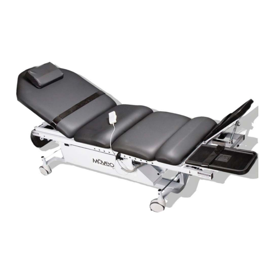
Mōveo™ XP 2- NOMENCLATURE 2.1 MŌVEO™ XP EXTERNAL TABLE COMPONENTS 1. 1. 2. 2. 9. 9. 8. 8. 3. 3. 5. 5. 4. 4. 7. 7. FIGURE 2.1 SIDE VIEW FIGURE 2.1 SIDE VIEW 6. 6. Back Rest Release Bar Foot Plates Head Rest Foot Plate Lock Knob... - Page 11 Mōveo™ XP 2- NOMENCLATURE 2.1 MŌVEO™ XP EXTERNAL TABLE COMPONENTS (CONTINUED) 1. 1. 2. 2. FIGURE 2.3 BACK REST VIEW FIGURE 2.3 BACK REST VIEW Back Rest Release Bar Cando Exercise Band Attachment Points and Winding Cleat 2.2 TABLE COMPONENT DESCRIPTIONS 2.2 TABLE COMPONENT DESCRIPTIONS Head Rest During exercise, the Head Rest pillow supports the head and neck of the patient.
- Page 12 Mōveo™ XP 2- NOMENCLATURE 2.2 TABLE COMPONENT DESCRIPTIONS (CONTINUED) Ankle Support Pad This pad provide comfortable support for the patient before, during, and after exercise. Caster Four independently moving caster wheels allow the table to be positioned close to the patient's bed or wheelchair before transfer and away from the patient's bed before exercise.
- Page 13 Mōveo™ XP 2- NOMENCLATURE 2.3 TABLE SYMBOL DEFINITIONS The purpose of the Weight Distribution Weight Distribution Chart Chart is to illustrate the correlation between the patient's body weight and the degree of incline on the Degree of Incline Mōveo™ XP, for more information on this chart, see page 16.
-
Page 14: Hand Controller
2- NOMENCLATURE Mōveo™ XP 2.4 HAND CONTROLLER 5. 5. 2. 2. 6. 6. 3. 3. 7. 7. 4. 4. FIGURE 2.4 HAND CONTROLLER FIGURE 2.4 HAND CONTROLLER (Iluminates Only if Battery Backup is Tilt Backward (DOWN Arrow) Button Present and a button is pressed) Raise Patient (UP Arrow) Button Raise Patient (UP Arrow) Button Tilt Forward (UP Arrow) Button... - Page 15 Mōveo™ XP Tilt Backward (DOWN Arrow) Button Press the button to tilt the table backward. Lower Patient (DOWN Arrow) Button Press the button to lower the table. The table can be lowered to a height of 57.15 cm (22.5").
-
Page 16: 3- Specifications
Mōveo™ XP 3- SPECIFICATIONS 3.1 PHYSICAL SPECIFICATIONS 57.15 - 97.79 cm 57.15 - 97.79 cm 22.5 - 38.5" 22.5 - 38.5" FIGURE 3.1 FIGURE 3.1 40.64 cm 40.64 cm 40.64 cm 40.64 cm 22.86 cm 22.86 cm 88.9 cm 88.9 cm 16"... -
Page 17: Controller Specifications
Mōveo™ XP 3- SPECIFICATIONS 3.2 TABLE SPECIFICATIONS Parameter Parameter 120V 120V Parameter Parameter 120V 120V Voltage Frequency Voltage Frequency 120 VAC -60Hz 120 VAC -60Hz Length (with Foot Plates Length (with Foot Plates 256.54 cm (101") 256.54 cm (101") down) down) Current Consumption Current Consumption... -
Page 18: Battery Backup Specifications
Mōveo™ XP 3- SPECIFICATIONS 3.5 BATTERY BACKUP SPECIFICATIONS 3.5 BATTERY BACKUP SPECIFICATIONS Parameter Parameter 120V 120V Type of Battery Type of Battery NiMH NiMH Input Input 24 VDC 24 VDC Output Output 24 VDC 24 VDC Rated Capacity Rated Capacity 4.5 Ah 4.5 Ah Internal Resistance... -
Page 19: Description Of Device Markings
Mōveo™ XP 3- SPECIFICATIONS 3.6 DESCRIPTION OF DEVICE MARKINGS 3.6 DESCRIPTION OF DEVICE MARKINGS The markings on the Mōveo ™ XP are assurance of its conformity to the highest applicable standards of medical equipment safety and electromagnetic compatibility. The following markings appear on the device: Listed by Intertek Testing Services NA Inc. -
Page 20: 4- Troubleshooting
This will ensure the test is performed to plate locks into place. While holding the foot plate plate locks into place. While holding the foot plate Chattanooga Group standards and enable Chattanooga Group standards and enable in one hand, press the lever of each foot plate in one hand, press the lever of each foot plate proper readings. -
Page 21: Electrical Safety
Mōveo™ XP 4- TROUBLESHOOTING NOTE: 4.3 ELECTRICAL SAFETY Ground Continuity and Leakage tests are This table has been tested to UL 60601-1, performed to verify the table meets the Standard for Safety for Medical Equipment. requirements listed. NOTE: NOTE: Test methods must comply with UL 60601-1. This device complies with current leakage, This device complies with current leakage, ground continuity, and dielectric withstand... -
Page 22: Limit Switch Test
Mōveo™ XP 4- TROUBLESHOOTING 4.7 LIMIT SWITCH TEST 3. 3. Set the multimeter to Ω or the continuity setting. A. Equipment Required 4. Attach the black lead of the multimeter to the • Multimeter cathode and the red lead to the anode of B. -
Page 23: Problem Solving
4- TROUBLESHOOTING Mōveo™ XP 4.10 PROBLEM SOLVING Problem Possible Cause Possible Solution Table will not move up or down - verify Mains Power - no voltage - replace hand controller - hand controller damaged - plug not making contact - verify the Mains Power cord is well seated - actuator malfunction - replace actuator... - Page 24 Mōveo™ XP 4- TROUBLESHOOTING 4.11 PROBLEM SOLVING (CONTINUED) Problem Possible Cause Possible Solution Table will not elevate under load or - elevation actuator is failing - replace actuator maintain elevation under load Table will not tilt under load or - tilt actuator is failing - replace actuator maintain tilt under load Back rest release bar is released and...
-
Page 25: 5- Removal And Replacement
5- REMOVAL AND REPLACEMENT Mōveo™ XP Unplug the unit from the power source before attempting removal or replacement procedures to prevent electrical shock. 5.1 HAND CONTROL REMOVAL AND REPLACEMENT A. Part Number ............80985 FASTENER B. Equipment Required • Flat Head Screwdriver •... -
Page 26: Controller Removal And Replacement
Mōveo™ XP 5- REMOVAL AND REPLACEMENT 5.2 CONTROLLER REMOVAL AND REPLACEMENT A. Part Numbers • 80983 ..............120V B. Tools and Equipment Required GROUND WIRE CONNECTION • 1/4" Combination Wrench • 3/8" Combination Wrench • Wire cutters • #20 TORX Wrench •... - Page 27 Mōveo™ XP 5- REMOVAL AND REPLACEMENT 5.2 CONTROLLER REMOVAL AND REPLACEMENT (CONTINUED) 5. If the controller has a battery, remove 5. If the controller has a battery, remove the battery back up power cord from the battery back up power cord from port 13 on the controller and release it port 13 on the controller and release it from the clip, then continue the removal...
-
Page 28: Elevation Actuator Removal And Replacement
5- REMOVAL AND REPLACEMENT Mōveo™ XP 5.3 ELEVATION ACTUATOR REMOVAL AND REPLACEMENT A. Part Number .......... 80990 B. Tools and Equipment Required • 6 mm Allen Wrench • 17 mm Combination Wrench • Wire Cutters • Flat Head Screwdriver • #2 Phillips Head Screwdriver •... - Page 29 Mōveo™ XP 5- REMOVAL AND REPLACEMENT 5.3 ELEVATION ACTUATOR REMOVAL AND REPLACEMENT(CONTINUED) 5. Remove the nuts and bolts that 5. Remove the nuts and bolts that secure the actuator to the brackets on the secure the actuator to the brackets on the frame at the top and bottom of the frame at the top and bottom of the actuator using a 6 mm allen and a 17 mm...
-
Page 30: Tilt Actuator Removal And Replacement
5- REMOVAL AND REPLACEMENT Mōveo™ XP 5.4 TILT ACTUATOR REMOVAL AND REPLACEMENT A. Part Number ..........80982 B. Tools and Equipment Required • 6mm Allen Wrench • 17mm Combination Wrench • Wire cutters • Flat Head Screwdriver • #2 Phillips Head Screwdriver •... - Page 31 Mōveo™ XP 5.4 TILT ACTUATOR REMOVAL AND REPLACEMENT (CONTINUED) 5. Enlist help to support the top frame of the 5. Enlist help to support the top frame of the table until the rod end of the actuator has table until the rod end of the actuator has been disconnected.
-
Page 32: And S-3 Limit Switch Removal And Replacement
5- REMOVAL AND REPLACEMENT Mōveo™ XP 5.5 S-1 AND S-3 LIMIT SWITCH REMOVAL AND REPLACEMENT A. Part Number ......... 80881 B. Tools and Equipment Required • #2 Phillips Head Screwdriver • #1 Phillips Head Screwdriver • 3/8" Combination Wrench • 1/4" Combination Wrench 1. - Page 33 Mōveo™ XP 5- REMOVAL AND REPLACEMENT 5.5 S-1 AND S-3 LIMIT SWITCH REMOVAL AND REPLACEMENT (CONTINUED) 5. Using a #1 phillips head screwdriver and a 5. Using a #1 phillips head screwdriver and a 1/4" 1/4" combination combination wrench, remove the 2 wrench, remove the 2 screws and nuts that hold both of the limit screws and nuts that hold both of the limit...
-
Page 34: Limit Switch Removal And Replacement
5- REMOVAL AND REPLACEMENT Mōveo™ XP 5.6 S-2 LIMIT SWITCH REMOVAL AND REPLACEMENT A. Part Number ......... 74089 B. Tools and Equipment Required • #1 Phillips Head Screwdriver • 1/4" Combination Wrench SCREWS 1. Lock the casters on the table. 1. - Page 35 Mōveo™ XP 5- REMOVAL AND REPLACEMENT 5.6 S-2 LIMIT SWITCH REMOVAL AND REPLACEMENT (CONTINUED) SUPPORT BAR 5. Reverse steps 1-3 for installation of the 5. Reverse steps 1-3 for installation of the switch. switch. NOTE: NOTE: The arm of the limit switch should make The arm of the limit switch should make contact and be pushed down slightly by the contact and be pushed down slightly by the...
-
Page 36: Tilt And Elevation Diode Removal And Replacement
5- REMOVAL AND REPLACEMENT Mōveo™ XP 5.7 TILT AND ELEVATION DIODE REMOVAL GRAY HEAT AND REPLACEMENT SHOULDER WASHER A. Part Number ........80873 B. Tools and Equipment Required • Flat Head Screwdriver • Wire Cutters • #1 Phillips Head Screwdriver •... -
Page 37: Brake Removal And Replacement
5- REMOVAL AND REPLACEMENT Mōveo™ XP 5.8 BRAKE REMOVAL AND REPLACEMENT A. Part Number .......... 80948 B. Tools and Equipment Required • 1/8" T-handle Allen Wrench • 7/16" Combination Wrench 1. Lock the casters and unplug the table 1. Lock the casters and unplug the table from the Mains Power supply. - Page 38 Mōveo™ XP 5- REMOVAL AND REPLACEMENT 5.8 BRAKE REMOVAL AND REPLACEMENT (CONTINUED) 5. Swivel the brake and remove the collar 5. Swivel the brake and remove the collar locks from both rods. locks from both rods. Refer to Figure 5.28. Refer to Figure 5.28.
-
Page 39: Removal And Replacement
5- REMOVAL AND REPLACEMENT Mōveo™ XP 5.9 MECHLOK REMOVAL AND REPLACEMENT A. Part Number........65471 B. Tools and Equipment Required • Small Flat Head Screwdriver • 9/16" Combination Wrench (2) 1. Press the lever of the release mechanism 1. Press the lever of the release mechanism on the on the Mechlok and pull the barrel up and pull the barrel up... -
Page 40: Gas Spring Removal And Replacement
5- REMOVAL AND REPLACEMENT Mōveo™ XP 5.10 GAS SPRING REMOVAL AND REPLACEMENT A. Part Number ..........80931 B. Tools and Equipment Required • 9/16" Combination Wrench (2) NOTE: NOTE: If the gas spring is not functioning and the If the gas spring is not functioning and the back rest is in the prone position, remove back rest is in the prone position, remove the key pins from both sides of the table... -
Page 41: Battery Removal And Replacement
Battery Backup is significantly reduced, the service life of the Battery Backup is exceeded and should be replaced with a new Chattanooga Group Battery Backup. Never attempt to rebuild the Battery Backup. Properly dispose of old Battery Backup. -
Page 42: 6- Maintenance
6- MAINTENANCE Mōveo™ XP 6.1 CLEANING LUBRICATION POINTS After each use, clean the table using a soft cloth dampened with water and a mild antibacterial detergent or hospital-approved detergent. 6.2 PREVENTATIVE MAINTENANCE 1. The Mōveo™ XP should be placed on a regular maintenance and inspection schedule based on the practices of the health care facility. -
Page 43: Service
• Contact person with Phone and Fax Numbers • Billing information • Detailed Description of Problem or Symptoms 2. Copy of original invoice issued at purchase of the unit. 3. Contact your dealer or Chattanooga Group for service instructions. 4717 Adams Road Hixson, TN 37343 USA 1-423-870-2281... -
Page 44: 7- Parts
Mōveo™ XP 7- PARTS 7.1 MŌVEO™ XP BASE ASSEMBLY NOTE ITEM #3: DETAIL VIEW OF SWITCH ASSEMBLY PART DESCRIPTION QTY. PART DESCRIPTION QTY. 64130 Nut 5/16 - 18 Acorn PLT 80976 Gull wing base weldment 61883 Plug Heyco #2723 DP 1093 80963 Linkage Front Assy 80949... -
Page 45: Mōveo™ Xp Base Assembly (Continued)
Mōveo™ XP 7- PARTS 7.2 MŌVEO™ XP BASE ASSEMBLY (CONTINUED) DETAIL B DETAIL A PART DESCRIPTION QTY. PART DESCRIPTION QTY. 80974 Base Assembly 80873 Diode 20A 1200 PRV to 220 AC 80836 Support Frame Weldment 80952 Heat Sink 80990 SKF Runner Elevation 71318 Screw 6 - 32 x 3/4 Pan HD Phil 80941... -
Page 46: Mōveo™ Xp Base Assembly (Continued)
7- PARTS Mōveo™ XP 7.3 MŌVEO™ XP BASE ASSEMBLY (CONTINUED) PART DESCRIPTION QTY. 87546 Nut 3/8-16 ESNA 65166 Fasteners PLS BLK M30-0630-08 80992 Sub Assembly 63360 Bearing 3/4 SBPP204 - 12 80886 Side Cover Left 80885 Side Cover Right 80851 Cart Bin Spacer Drilled 80930 Angle Storage Bin... -
Page 47: Mōveo™ Xp Top Frame Assembly
Mōveo™ XP 7- PARTS 7.4 MŌVEO™ XP TOP FRAME ASSEMBLY PART DESCRIPTION QTY. PART DESCRIPTION QTY. 80965 Bracket Brake Mount 80835 Top Frame Weldment 80948 Carriage Brake 80932 Cover Top Fame 80989 Rod Brake Mount 80935 Bar Foot Plate Support 20658 Rivet ALS 4 - 420-165-1/4 - 20 80937... -
Page 48: Mōveo™ Xp Carriage Assembly
Mōveo™ XP 7- PARTS 7.5 MŌVEO™ XP CARRIAGE ASSEMBLY PART DESCRIPTION QTY. PART DESCRIPTION QTY. 87616 Collar shaft 3/8 ID PLT C37 60394 Pin Spring 3/16 OD x 3/4 Len 60016 Screw 1/4 -20 x 3/4 Hx CP PLT 21391 Washer 5/16 Flat Zinc Plated 21829 Screw 1/4 - 20 x 1/2 soc HD CAP... -
Page 49: Mōveo™ Xp Final Assembly
7- PARTS Mōveo™ XP 7.6 MŌVEO™ XP FINAL ASSEMBLY TOP FRAME BASE PART DESCRIPTION QTY. 80924 T-handle pin drilled 80922 Wire NYL - CTD W/Loop 80921 Ring Split STL Zinc 66058 Rivet 3/16 DX 440 Done Steel 80918 Seat Board 80866 Ankle Board 80897... -
Page 50: 8- Wiring Schematic
Mōveo™ XP 8- SCHEMATICS 8.1 WIRING SCHEMATICS 8.1 WIRING SCHEMATICS HAND CONTROL WIRING SCHEMATIC FOR MOVEO XP TABLE PORT 9 CONTROLLER PORT 2 PORT PORT PORT 1 TERMINAL STRIP MAINS BATTERY PACK INPUT GREEN/ (OPTIONAL) YELLOW FRAME OF TABLE BLUE... -
Page 51: 9- Warranty
9 - WARRANTY United States of America Chattanooga Group (“Company”) warrants that the Mōveo™ XP (“Product”) is free of defects in material and workmanship. This warranty shall remain in effect for one year (12 months) from the date of original consumer purchase. - Page 54 ISO 13485 Certifi ed 4717 Adams Road P.O. Box 489 Hixson, TN 37343 U.S.A. 1-423-870-2281 1-800-592-7329 U.S.A. 1-423-875-5497 chattgroup.com © 2007 Chattanooga Group 81039A...
Need help?
Do you have a question about the MOVEO XP and is the answer not in the manual?
Questions and answers