Advertisement
Quick Links
WARNING
NOTICE:
TECHNICAL SPECIFICATIONS - ASSEMBLY PROCEDURE
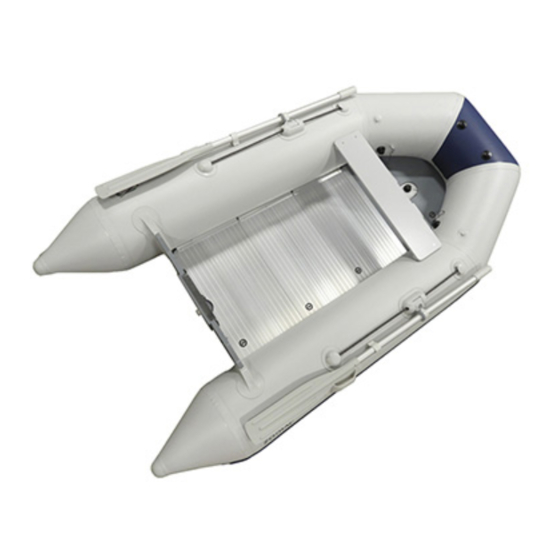
WAVE 275 Roll Up – WAVE 275 Aero
WAVE 310 HD – WAVE 310 Aero – WAVE 310 Compact
Assembly procedure
Check on unpacking
Assembly
Inflation system
Inflation
CAREFULLY READ THIS MANUAL BEFORE OPERATING YOUR
BOAT.
THIS OWNER'S MANUAL IS IN TWO VOLUMES THAT MUST BE
KEPT TOGETHER.
THE OWNER'S MANUAL IS IN TWO VOLUMES:
- VOLUME 1
DEALS
WITH
OPERATING
RECOMMENDATIONS THAT MUST BE OBSERVED.
- VOLUME 2
DEALS WITH TECHNICAL SPECIFICATIONS AND ASSEMBLY
PROCEDURE OF THE BOAT AND ITS EQUIPMENT.
VOLUME 2
CONTENTS
Page
3
3
4-6
7
8-9
1 / 12
PRECAUTIONS
AND
Pressure
Assembly of equipment
Deflation - folding the boat
General description
E
N
G
L
I
S
H
SAFETY
Page
10
11
12
I -VI
Advertisement


Need help?
Do you have a question about the WAVE 275 Roll Up and is the answer not in the manual?
Questions and answers