BIRO AFMG-24 Operating And Service Manual
Hide thumbs
Also See for AFMG-24:
- Operating and service manual (27 pages) ,
- Operating and service manual (30 pages)
Table of Contents

Subscribe to Our Youtube Channel
Related Manuals for BIRO AFMG-24


Summary of Contents for BIRO AFMG-24
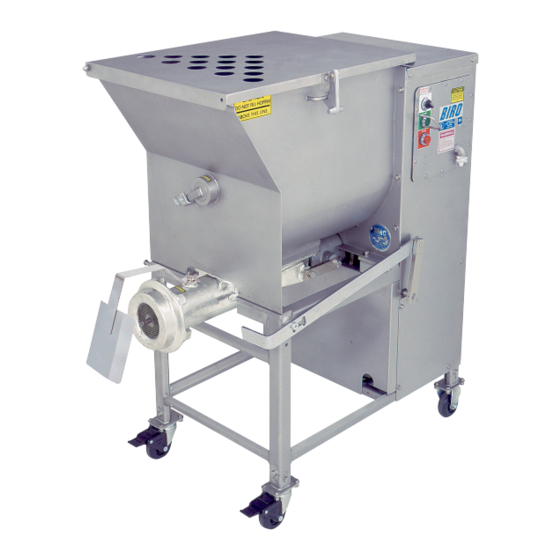
- Page 1 Model AFMG-24 MINI AUTOMATIC MIXER GRINDER/CHOPPER OPERATING SERVICE MANUAL IMPORTANT NOTICE This Manual contains important safety instructions which must be strictly followed when using this equipment. Item No. 56224 AFMG-24-220-8-21-19...
-
Page 3: Table Of Contents
TABLE OF CONTENTS: PAGE NOTICE TO OWNERS AND OPERATORS ..........SAFETY TIPS . -
Page 4: Notice To Owners And Operators
No one should use or service this machine without proper training and supervision. All operators should be thoroughly familiar with the procedures contained in this Manual. Even so, BIRO cannot anticipate every circumstance or environment in which its products will be used. You, the owner... -
Page 5: Safety Tips
NEVER Alter This Machine From its Original Form as Shipped From Factory. DO NOT Operate Machine With Missing Parts. • PROMPTLY REPLACE Any Worn or Illegible Warning Labels. • ALWAYS Read Operation and Service Manual BEFORE Operating, Cleaning, or Servicing. • USE ONLY BIRO Parts and Accessories Properly Installed. -
Page 6: Installation
NEVER Operate Without all Warning Labels Attached and Owner/Operator Manual Available to the Operator. • USE ONLY BIRO Parts and Accessories Properly Installed. UNCRATING AND SET UP 1. Read this Manual thoroughly before installation and operation. Do not proceed with installation and operation if you have any questions or do not understand anything in this Manual. -
Page 7: Motor Wiring And Electrical Requirements
No. 10 WIRE. If the length of the circuit from the power source to the grinder is long, increase the size of the wire gauge to the next larger size. i. The BIRO Manufacturing Company is not responsible for permanent wiring, connection or installation. NOTE TO OWNER AND ELECTRICIAN: IF THIS MACHINE IS NOT CORD... - Page 8 16. Check placement of all warning labels and Manual. Machine is now ready for trained operators to process product. 17. Use meat deflector attached to grinding bowl to eliminate meat splatter. 18. Contact your local Distributor or BIRO directly if you have any questions or problems with the installation or operation of this machine.
-
Page 9: Operation
OPERATION ROTATING GRINDING AUGER & ROTATING MIXING PADDLES TO AVOID SERIOUS PERSONAL INJURY • ONLY Properly Trained Personnel Should Use This Equipment. • NEVER Place Hands into Machine Input or Output Openings. • NEVER Open Machine During Operation. • DO NOT Grind Frozen Product. •... -
Page 10: Cleaning
Electrical Components. • ALWAYS Thoroughly Clean Equipment at Least Daily. CLEANING THE BIRO MIXER-GRINDER l. Disconnect mixer grinder from power-source and perform lockout/tagout procedures. 2. Remove grinding bowl end ring, breaker plate, knife and grinding auger. 3. Remove mixing paddle. Be sure front most paddle arm is pointing up. Loosen the thumb screw on the mix- er paddle lock arm (Item No. -
Page 11: Maintenance
PROMPTLY REPLACE Any Worn or Illegible Warning Labels. • USE ONLY GENUINE BIRO Parts and Accessories Properly Installed. A. MIXING PADDLE INSTALLATION 1. Check that mixer paddle drive pin (Item No. 53516) in the mixer paddle drive shaft (Item No. 53955) is positioned vertically. -
Page 12: Grinder Knives And Plates
In addition, such practice will probably break the new member. Available Grinder knives and plates for Model AFMG-24 MC32-17 Knife, Size 32, Standard Disposable Plate, Size 32, ⅛”... -
Page 14: Parts Diagrams
FRAME AND CASE FRAME & CASE FASTENERS ADJUSTABLE LEGS TO FRAME Item No. HHS067S Hex head screw, ⅜-16 x ¾, SS, (8 ea.) HN35S Hex nut, ⅜-16, SS, (8 ea.) LW20S Lock washer, ⅜”, SS, (8 ea.) TRANSMISSION MOUNTING PLATE SUPPORTS TO FRAME Item No. -
Page 15: Mixer
MIXER Fig. Item No. Description 53568 Mixer paddle lock set screw 53594 Lock arm radial bearing 53517 Lock arm thrust bearing 53852 Lock arm assembly, w/ bearings 53953 Seal, mixer drive shaft thru tub 56039 Product mixer safety cover 56040 Product mixer tub, no side inlet 56121 Product mixer tub, RH side inlet... -
Page 16: Power Transmissions And Journal Box
POWER TRANSMISSION POWER TRANSMISSION FASTENERS MIXER TRANSMISSION TO MOUNTING PLATE JOURNAL BOX TO MOUNTING PLATE Item No. Item No. HHS126S Hex head screw, ½-13 x 1¼, SS, (4 ea.) HHS070S Hex head screw, ⅜-16 x 1, SS, (4 ea.) LW30S Lock washer, ½”, SS, (4 ea.) LW20S Lock washer, ⅜, SS, (4 ea.) - Page 17 Fig. Item No. Description Fig. Item No. Description 56211-1 Driven clutch engagement bushing 56287 Motor 7½HP, 3Ph, 208-230/460V, 60Hz SSB50PS 56286 Shoulder bolt, ⅜-16 x ⅜ Motor 5HP, 3Ph, 208-230/460V, 60Hz H310A 56270 Bearing assembly (journal box, front) Link engage handle 53785 56288 Seal, journal box (front, auger drive)
-
Page 20: Power Controls (Electrical)
POWER CONTROLS Fig. Item No. Description Fig. Item No. Description 42MC-Y73 Start button, Green H281EE-52 Overload, B18K-L 5.5-8.5Amps 5HP, 3Ph 460-575V, 60Hz 42MC-Y74 Stop button, Red 51991 H281EE-53 Overload, B18K-M 8-12Amps Fuse holder 7½HP, 3Ph 460-575V, 60Hz 56301G Watertight 90° cord connector 35375 End barrier, Terminal block Cover control panel... -
Page 21: Retrofit Aeg Contactors In Control Box
RETROFIT FOR AEG CONTACTORS IN AFMG-24 CONTROL BOX SERIAL NO. 20001 ON The magnetic contactors and overloads in the AFMG-24 have been changed to AEG electrical components. These controls are interchangeable with the old controls with some minor modifications. Use the following kit numbers when replacing previous contactors with AEG. -
Page 22: Optional Stainless Steel Bowls, Augers & Rings (114Mm Unger & Enterprise)
OPTIONAL STAINLESS STEEL BOWLS, AUGERS & PINS 114mm UNGER SYSTEM ENTERPRISE SYSTEM (Shown Above) (NOT Shown) Item No. Description Item No. Description HR42/48S FHS33S Shear pin fastener End ring, SS HHS010S 54278-CTNS Auger assembly, SS Hex head screw, 10-32 x ⅜, SS HK114 56049S Knife drive pin, 114mm Unger... -
Page 23: Items Required For Tandem Operation
ITEMS REQUIRED FOR TANDEM OPERATION NOTE: THESE ARE DESIGNED TO WORK ON BIRO EQUIPMENT OR OTHER MANUAL AND AUTO FEED GRINDERS OF COMPARABLE PLATE SIZE CONNECTING BRACKET PLASTIC KNOB ASSEMBLY PART No. 272-7-1 PART No.53552-2A INPUT HOPPER FEED TUBE SEAL BOWL OF No. -
Page 24: Footswitches, Pneumatic & Electric
OPTIONAL PNEUMATIC FOOT SWITCH... - Page 25 OPTIONAL ELECTRIC FOOT SWITCH...
-
Page 26: Optional Equipment Illustrated
OPTIONAL Model AFMG-24 shown with Optional L.H. Model AFMG-24 shown with Optional R.H. Inlet Inlet Item 56124NE, Optional Casters Item Item 56121NE, Optional Casters Item 56007NE or 56007NE or Optional Stainless Steel Casters Optional Stainless Steel Casters Item 56007SNE, Item 56007SNE... -
Page 27: Warning Label Locations On Machine
SAFETY LABEL LOCATIONS... -
Page 28: Tandem Operation Illustration For 90° Inlet
TANDEM OPERATION ILLUSTRATION FOR 90° INLET... -
Page 29: Tandem Connection Illustration
CONNECTION INSTRUCTIONS FOR TANDEM OPERATIONS AFMG-24 into AFMG-24 or Heavy Horsepower Grinder into AFMG-24 Step 1. Remove Lock Knobs, Item No. 14688; Outer disc, Item No. 54303 and Side Entrance Seal, Item No. 56167 from the inlet tube of the Second Grind Machine. Clean out the tube if necessary. -
Page 30: Mixer Drive Shaft Seal Replacement
11. Wait, allow for 10 minutes set up time. Remove Wedge and Ring. 12. Apply a small amount of NSF approved silicone sealant, Biro Item No. 400 around the outside edge of the Seal. Wipe away excess silicone sealant. The 3 fluid ounce tube of Sealant contains enough to complete 30 Assemblies. -
Page 31: Operator's Signature Page
OPERATOR’S SIGNATURE PAGE WARNING READ AND UNDERSTAND THIS ENTIRE MANUAL BEFORE SIGNING BELOW MY SIGNATURE ATTESTS THAT I HAVE COMPLETELY READ AND UNDERSTAND THIS MANUAL. I REALIZE THAT THIS MACHINE, IF OPERATED CARELESSLY, CAN CAUSE SERIOUS INJURY TO MYSELF AND OTHERS. NAME (PRINT) SIGNATURE SUPERVISOR’S... -
Page 32: Limited Warranty
BIRO is not responsible for service charges or labor required to replace any part covered by this limited warranty or for any damages resulting from misuse (Grinding of Frozen Product for Example), abuse, lack of proper or recommended service.
Need help?
Do you have a question about the AFMG-24 and is the answer not in the manual?
Questions and answers