
Related Manuals for Aim STANAG3910


Summary of Contents for Aim STANAG3910
- Page 1 ANET3910-EN STANAG3910 Electrical Test & Simulation Module for Standard Ethernet Users Manual V01.21 Rev. A March 2018...
- Page 3 ANET3910-EN User’s Manual for Single Stream STANAG3910-Electrical Ethernet-Interface Users Manual V01.21 Rev. A March 2018 AIM No. 60-13E25-16-0121-A ANET3910-EN User’s Manual...
- Page 4 Notice: The information that is provided in this document is believed to be accurate. No responsibility is assumed by AIM GmbH for its use. No license or rights are granted by implication in connection therewith. Specifications are subject to change without notice.
- Page 5 DOCUMENT HISTORY The following table defines the history of this document. Version Cover Date Created by Description V01.00 Rev-A 18.06.2015 F. Scherer First Version V01.00 Rev-B 20.07.2015 F. Scherer Some minor changes Modification related to the changed V01.01 Rev-1 11.07.2016 F.
- Page 6 THIS PAGE IS INTENTIONALLY LEFT BLANK ANET3910-EN User’s Manual...
-
Page 7: Table Of Contents
Transformer Coupling ....................29 3.1.8.3 Network Emulation Coupling ..................30 3.1.8.4 Isolated Coupling......................30 3.1.9 Connecting the ANET3910-EN to the STANAG3910 electrical HS-Bus ......31 Breakout Cables ........................32 3.2.1 Breakout Cable ACB-HD15-1 ....................32 3.2.2 Breakout Cable ACB3910-EN ....................33 Structure of the ANET3910-EN ................ - Page 8 Low Speed Physical Interface & Coupling Modes ..............37 4.5.2 Physical STANAG3910 I/O Interface ..................39 4.5.2.1 Electrical characteristics ....................39 4.5.2.2 Structure of electrical STANAG3910 Bus ..............39 4.5.3 Discrete I/Os ......................... 40 ASP Section ..........................41 IRIG-B and Time Code Section ....................42 4.7.1 Timecode Encoder/Decoder ....................
- Page 9 Figure 9.1-3 ANET Table Adapter ................57 LIST OF TABLES Figure Title Page Table 2.2.1.2-1 Pinout STANAG3910 Interface Connector ..........7 Table 2.2.1.3-2 Pinout Auxiliary Connector ..............8 Table 3.1.99-1 Pinout DSUB9 connector ............... 31 Table 4.7.1-1 Time Tag Format ..................42 ANET3910-EN User’s Manual...
- Page 10 THIS PAGE INTENTIONALLY LEFT BLANK ANET3910-EN User’s Manual viii...
-
Page 11: Introduction
For programming information please refer to the documents listed in the ‘Applicable Documents’ section. The ANET3910-EN modules are members of AIM's new family of advanced Ethernet connected standalone modules for analysing, simulating, monitoring and testing of avionic data bus systems. -
Page 12: Applicable Documents
Division Command/Response Multiplex Data Bus, Notice 1-4, January 1996 prEN3910-001, Edition P1, January 1996 Aerospace series High speed data transmission under STANAG3838 or fibre equivalent control 1.2.2 Product Specific Documents AIM – STANAG-3910 Reference Manual - Detailed description of the programming interface (API). ANET3910-EN User’s Manual... -
Page 13: Installation
The software is available on DVD from AIM or via a download from AIM-Online, instructions how to obtain the BSP via a download from AIM-Online are described in the following chapter. To install the BSP software from the AIM provided DVD or a download from AIM-Online (www.aim-online.com) -
Page 14: Figure 2-1 Bsp Setup
The BSP installation will result in the creation of the following Program Folder icons which can be found by going to Start | All Programs | AIM GmbH | STANAG3910 Windows BSP 12.x.y: The AIM GmbH sub-directory will be located by default in the directory C:\Program Files\. - Page 15 2. Installation The directories contain the following (Among others): Add-Ons Additional software or source code distributed with the BSP (e.g. the AIM Network Detection Tool). Lib32, lib62 Application Programming Interface DLL-Files and Libraries required to develop an application for Windows systems...
-
Page 16: Hardware Installation
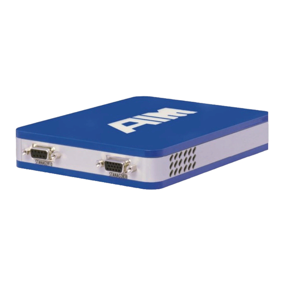
The external interface of the ANET3910-EN consists of the following connectors: • Front panel - STANAG-3838 One 15-pin High Density DSUB connector - STANAG3910 Frontend Connector One 9-pin DSUB connector • Back panel - Trigger I/O, Discretes, IRIG I/O Auxiliary 15-pin High Density DSUB connector for the Trigger Input/... -
Page 17: Stanag3838/Mil-Std-1553 Interface Connectors
STANAG-3838 Secondary Channel (true) MIL_BUS_SEC# STANAG-3838 Secondary Channel (complement) 6 - 15 Reserved 2.2.1.2 Electrical STANAG3910 Interface Connector For connecting the electrical STANAG3910 Bus to the ANET3910-EN Front end, a DSUB9 connector is provided. The pinout is shown below: Pin No. Signal... -
Page 18: Auxiliary Connector Hd Dsub15
(front view) 9 Pin DSUB (female) Figure 2-5 DSUB9 (front view) Note: The Aircraft-GND is galvanic de-coupled from the ANET3910-EN on board GND, it ends at the primary side from the 3910 electrical transformer. 2.2.1.3 Auxiliary Connector HD DSUB15 On the ANET3910-EN a 15-pin female High Density DSUB auxiliary connector is implemented for the Trigger IN/OUT, IRIG IN/OUT and Discrete I/O signals. -
Page 19: Dc Power In Connector
2. Installation 2.2.1.5 DC Power IN connector The DC Power in plug is a DC panel socket with a 2,5mm centre pin. The nominal input voltage is 12V DC via the centre pin.. Figure 2-6 DC panel socket 2.2.1.6 RJ45 Ethernet connector For the Ethernet connection a standard RJ45 plug is provided at the back panel. -
Page 20: Module-Powering And Status Indication (Led's)
Activity status (yellow) and the other LED one for the speed detection (green). 2.2.2.2 Module Status Indicator On top of the ANET3910-EN cover, the transparent AIM Logo is illuminated and indicates the status from the ANET3910-EN as following: Power ON/OFF / Normal operation... -
Page 21: Powering The Module
2. Installation 2.2.2.3 Powering the module …15V In general any external power supply (wall adapter) providing 9V can be used to power the ANET3910-EN. An external 12V power supply is recommended and is provided with an ANET3910-EN module. All onboard voltages are generated from this voltage. The module is immediately powered on, if the DC Power is available (i.e. - Page 22 THIS PAGE INTENTIONALLY LEFT BLANK ANET3910-EN User’s Manual...
-
Page 23: Getting Started
3. Getting started 3 GETTING STARTED This chapter describes the configuration, maintenance and update of the ANET3910-EN and how to use the ANET3910-EN from a customer application and with AIMs PBA.pro Analyser Software. 3.1.1 Requirements The configuration of the ANET3910-EN module is via web application hosted by the ANET and therefore Operating System independent. -
Page 24: The Aim Network Detection Tool
ANET3910-EN modules in your network. The AIM Network Detection Tool makes use of Apple Bonjour, a freeware Zeroconf implementation. How to install and use Apple Bonjour and how to use the AIM Network Detection Tool is described in the following sections. -
Page 25: Using The Aim Network Detection Tool
PC. 3.1.3.2 Using the AIM Network Detection Tool The AIM Network Detection Tool is part of delivery and provided on the ANET3910-EN Software-DVD. Run the aim-net-finder.exe executable from the directory of the ANET3910-EN Software-DVD to start the AIM Network Detection Tool. After some... -
Page 26: Configuring Basic Properties
First of all you have to enter a user name and password on the login screen, the default login is: User Name: ‘user’ ‘aim’. Password: After a successful login, you will be forwarded to the System Overview page. This page shows a summary of the current system status as shown in the figure below. -
Page 27: Setting The Ip-Address
Make sure to adapt your applications to the new alias name. The default alias is ANET3910-<x>, x= Serial Number. 3. Getting started ANET3910-x User’s Manual 15 Note: It is recommended to change the password (default = “aim”) when using the ANET3910 module the first time. 3.1.4.2 Setting the IP-Address Click on the Network Settings tab in the navigation bar. -
Page 28: Configuring Wireless Network Interfaces
3.1.4.3 Configuring Wireless Network Interfaces The ANET3910-EN device offers support for an USB based Wi-Fi network device in order to connect the ANET3910-EN to a wireless network. From the time when the Wi-Fi USB device is attached to the USB port of the ANET3910-EN, the Network Settings tab will show an additional section that allows configuring the Wi-Fi device (See figure 3.1.4.2-1). -
Page 29: Figure 3-7 Anet Wireless Network Device Configuration
3. Getting started Figure 3-7 ANET Wireless Network Device Configuration Example: Setting up a wireless access point on Windows 8.x devices Devices running with a Microsoft Windows 8.x Operating System and featuring a Wi-Fi device can be used to create a wireless access point. The ANET3910-EN device can join this network. -
Page 30: Configure System Services
The ANS1553 basically offers an ‘endpoint’ or ‘service’ for applications which use the AIM 3910 ApiConnectToServer” call in order to establish a connection to an ANET3910- EN. That API function can either use the alias name or the IP address of an ANET3910-... -
Page 31: Discrete I/O
3. Getting started Figure 3-8 ANET Web Configuration Tool “Services” 3.1.4.5 Discrete I/O Click on the Discrete I/O tab in the navigation bar (see the figure below). Shows GPIO states. Figure 3-9 ANET Web Configuration Tool “Discrete I/O” 3.1.4.6 Check System Log-File Click on the Maintenance tab in the navigation bar (see the figure below). -
Page 32: Re-Boot Or Shutdown Over Ethernet
Tab to press the OK button on “Reset all settings now”. After resetting the settings, the password will be set to the factory default (“aim”), the Network Settings will be set to DHCP mode and the services SSH and ANS1553 will be enabled. -
Page 33: Figure 3-11 Anet Web Configuration Tool "Update Tab
3. Getting started location of the update file in the BSP is /Onboard-SW/update-components/. Figure 3-11 ANET Web Configuration Tool “Update tab” During the update is in progress the update status is shown, don’t close the Web Browser when the update is running. Figure 3-12 ANET Web Configuration Tool “Update is running”... -
Page 34: Figure 3-13 Anet Web Configuration Tool "Update Finished
Figure 3-13 ANET Web Configuration Tool “Update finished” Figure 3-14 ANET Web Configuration Tool “Update Log-File” ANET3910-EN User’s Manual... -
Page 35: Booting The Device Into Emergency Mode
You are able to connect to the ANET3910-EN device with your web browser now. 3.1.7 How to connect Applications to the ANET3910-EN The following chapters describe how to connect an ANET3910-EN with PBA.pro or any customer specific application using the AIM Application Programming Interface Library (API-Library). 3.1.7.1 Connect to a ANET3910-EN with PBA.pro Open the “Help\About\Settings”... -
Page 36: Connect To A Anet3910-En Using The Aim Api-Library
The figure below shows how it looks like for an ANET3910-EN. Figure 3-17 Connect to ANET3910 with PBA.pro 3.1.7.2 Connect to a ANET3910-EN using the AIM API-Library To connect to an ANET3910-EN via customer specific applications using the AIM Application Programming Interface Library (API-Library), the following steps are necessary. -
Page 37: Connecting The Anet3910-En To The Stanag3838 Low Speed Bus
3. Getting started a) To establish a network connection to an ANET3910-EN, with the AIM Network Server (ANS) running , the API function “ApiConnectToServer” has to be called. As already mentioned above, the alias name or IP Address must be passed as a parameter for proper initialisation of the API network connection. -
Page 38: Direct Coupling
Since a Direct Coupled stub provides only limited isolation in the event of a device (subsystem or terminal) short, Transformer Coupling is normally the recommended AIM provided Pigtail Connector method of connecting to the bus. Figure 3-18 Pigtail Connector Bus A... -
Page 39: Transformer Coupling
Bus Coupler 78Ω Termination Figure 3-21 Transformer Coupling 78 Ω Terminators Bus Coupler Bus Coupler (Bus A) (Bus B) Stub Length 20 Feet Max Bus is actually in coupler AIM Module Test Terminals Figure 3-22 Transformer Coupling ANET3910-EN Users Manual... -
Page 40: Network Emulation Coupling
3.1.8.3 Network Emulation Coupling Network Emulation Coupling is a special option for the ANET3910-EN. The AIM design includes on-board Bus Network circuitry that is software selectable. This allows the user to connect the Low Speed Bus directly to a single terminal device without the need for any bus coupling. -
Page 41: Connecting The Anet3910-En To The Stanag3910 Electrical Hs-Bus
3. Getting started 3.1.9 Connecting the ANET3910-EN to the STANAG3910 electrical HS-Bus The ANET3910-EN provides a STANAG3910 on board electrical Frontend. For connecting the electrical High-Speed Bus to the ANET3910-EN Front end, a DSUB9 connector is provided. The pinout of the DSUB9 connector is shown below: Pin No. -
Page 42: Breakout Cables
3.2 Breakout Cables 3.2.1 Breakout Cable ACB-HD15-1 Ready-made Adaptor Cable (2 metres) from 15 Pin High-Density D-Sub (ANET3910-EN side) to 2 x Twinax Connectors. Figure 3-25 Breakout Cable ACB-HD15-1 Signal Type MIL_BUS_PRI MILBUS Primary Channel (true) MIL_BUS_PRI# MILBUS Primary Channel (complement) Electrical Ground MIL_BUS_SEC MILBUS Secondary Channel (true) -
Page 43: Breakout Cable Acb3910-En
3. Getting started 3.2.2 Breakout Cable ACB3910-EN The ACB3910-EN is a ready-made Adaptor Cable (2 Metres) from 9 Pin D-Sub (APE3910-EN side) to 2 x BNC Connectors. Figure 3-26 Breakout Cable ACB3910-EN Note: The Aircraft-GND is connected to the DSUB9 metal cover as well, to have a good shielding and connection the PC Chassis-GND. - Page 44 THIS PAGE INTENTIONALLY LEFT BLANK ANET3910-EN User’s Manual...
-
Page 45: Structure Of The Anet3910-En
4. Structure of the ANET3910-EN 4 STRUCTURE OF THE ANET3910-EN The ANET3910-EN comprises the following main sections: System FPGA/SoC Global RAM LS-BIU Section Physical I/O Interface ASP Section IRIG-B-122 – Time Code Processor with Free Wheeling Function ... -
Page 46: Global Ram
Manchester error, framing error) via dedicated bits in an error status register. 4.4 HS BIU Section The HS-BIU consists of the SoC CPU-Core, the STANAG3910 Encoder/Decoder logic to handle the High Speed Bus protocol and the Trigger-Logic to handle the HS BM- Trigger-Output generation. -
Page 47: Physical I/O Interface
4. Structure of the ANET3910-EN 4.5 Physical I/O Interface Consist of a Dual redundant STANAG-3838/ MIL-STD-1553B (Low Speed) channel with programmable output Amplitude and Coupling Network and a dual redundant 3910 (High Speed) Fibre Optic channel. 4.5.1 Low Speed Physical Interface & Coupling Modes One dual redundant STANAG-3838/ MIL-STD-1553B interface is available, which implements a MILbus Transceiver with variable output amplitude capability. - Page 48 Figure 4-3 Diagram MILbus output amplitude versus amplitude settings The X-Axis (→) is the setting of the programmed amplitude values (0…255), whereas the Y-Axis (↑) is the output amplitude [VPP] on the Transformer coupled Stub (0…20VPP). This diagram shows a characteristic behaviour of the output amplitude, but exact settings might be slightly different.
-
Page 49: Physical Stanag3910 I/O Interface
4. Structure of the ANET3910-EN 4.5.2 Physical STANAG3910 I/O Interface The APX3910-EN provides an electrical STANAG3910 High Speed transceiver. 4.5.2.1 Electrical characteristics 50 Characteristic Input-Impedance: TX-Output Voltage: 6.0V ... 9.0V RX-Input Voltage: 0.15V ... 2.0V 4.5.2.2 Structure of electrical STANAG3910 Bus... -
Page 50: Discrete I/Os
4.5.3 Discrete I/Os The ANET3910 module provides eight user definable discrete I/O signals. Discrete input signals are always active whereas the discrete output signals are per default inactive. An open collector circuitry is used for the discrete output with approximately 4V provided by default. -
Page 51: Asp Section
4. Structure of the ANET3910-EN Off-Board User Voltage serial Customized Discrete Output Discrete IO-Pin Front Connector FPGA Output ANET3910 Board Figure 4-6 Discrete I/O-Pin off board user series resistor 4.6 ASP Section The Application Support Processor (ASP) is part of the dual core processor system in the FPGA/SoC and running under an embedded LINUX Operating System. -
Page 52: Irig-B And Time Code Section
4.7 IRIG-B and Time Code Section The main functions of the Time Code Processor (TCP) are: IRIG-B compatible Time Code Decoder function Time Code Encoder – IRIG-B compatible Time Encoder function 4.7.1 Timecode Encoder/Decoder The generated time code signal is an IRIG-B-122 compatible signal. The time code information can be used for time-tagging and multi-channel synchronization. -
Page 53: Time Tag Methods
No connection required Multiple AIM-Modules with no common synchronization requirement No connection required Single or multiple AIM-Module(s) with external IRIG-B source Connect external IRIG-B source to IRIG-IN and GND of all modules Multiple AIM-Modules with no external IRIG-B source internally... - Page 54 THIS PAGE INTENTIONALLY LEFT BLANK ANET3910-EN User’s Manual...
-
Page 55: Compiling And Running A Sample Project
API programming see the included 3910 programmers guide document. Note: To execute a pre-compiled sample program run 3910_sample_project.exe from within the sample directory : Start | All Programs | AIM GmbH | STANAG3910 Windows BSP 12.x.y | 3910_sample_project The 3910_sample_project program opens a board and provides a selection of sample functions to execute . -
Page 56: Figure 5-1 File Structure Sample Project
Right click the project and select Properties Select the C++ / General Additional Include Directories must contain the include directory c:\Program Files\AIM GmbH\STANAG3910 Windows BSP 12.x.y\include Then select the OK button Figure 5-2 Sample Project search paths ANET3910-EN User’s Manual... -
Page 57: Figure 5-3 Sample Project Pre-Processor Definitions
5. Compiling and running a Sample Project To add the proper pre-processor definition Right click the project and select Properties Select the C++ / Pre-processor Under Pre-processor Definitions, if not already included, enter _AIM_WINDOWS then select OK. Figure 5-3 Sample project pre-processor definitions ... -
Page 58: Figure 5-4 Sample Project Library Path
Figure 5-4 Sample project library path To Build and Execute a Sample Program Build | Rebuild Solution The executable will be stored in the Debug or Release subdirectory The api_mil.24.dll will be referenced from the Windows system directory Run the executable. ANET3910-EN User’s Manual... -
Page 59: Frequently Asked Questions
ANET3910-EN (indicated by red blinking LED). After power up, log into the Web Configuration Tool with your Web Browser. The emergency system accepts the default user ‘user’ and password ‘aim’. Go to the ‘Maintenance’ tab and press the ‘Reset To Factory Defaults’ button. This will reset the user name and password of the device. - Page 60 THIS PAGE INTENTIONALLY LEFT BLANK ANET3910-EN User’s Manual...
-
Page 61: Technical Data
Single implementation with bus switching logic (not redundant). Full error detection and indication inter word gap timer with 250ns resolution (nine bit). STANAG3910 Manchester Encoder with FCS Generator and error injection. Encoder Single Implementation with bus switching logic (not redundant) - Page 62 - Transformer coupled - Direct coupled - Network coupled (Transformer coupled with on-board resistor network emulation) - Isolated Characteristic Input-Impedance: 50 STANAG3910 Bus Interface TX-Output Voltage: 6.0V ... 9.0V RX-Input Voltage: 0.15V ... 2.0V For absolute time tagging, a special time code processor Time Tagging implements an IRIG-B-122 encoder/decoder.
- Page 63 Front panel: STANAG3838 Connector: - 15 pol. high density DSUB, female for STANAG3838 bus STANAG3910 Connectors: - 9 pol. DSUB, female for electrical STANAG3910 bus Buttons Power ON-OFF Emergency Boot TTL compatible Input Level, 1KΩ series resistor and fast ESD Trigger In protection.
- Page 64 Power Consumption Operational (IDLE): PIN = 8W Operational (50% Bus Load) PIN = 9W. Note: All measurements are done with a V =12V. 0°C…50°C Temperature Standard Temperature Range: Extended Temperature Range: -15°C…60°C Storage Temperature Range: -40°C…+85°C 0…95% non-condensing Humidity Dimensions Width x Length x High = 120 x 160 x 26mm (without connectors) Weight...
-
Page 65: Notes
8. Notes 8 NOTES 8.1 Acronyms Analog to Digital Converter ALBI ASP Local Bus Interface Advanced RISC Machine Application Support Processor Bus Interface Processor Bus Interface Unit Bus Monitor Board Software Package CCPMC Conduction Cooled PCI Mezzanine Card Common Mezzanine Card Family Digital to Analog Converter. - Page 66 THIS PAGE INTENTIONALLY LEFT BLANK ANET3910-EN User’s Manual...
-
Page 67: Appendix
9. Appendix 9 APPENDIX 9.1 ANET Table Adapter Panel For the ANET3910- D Module Variants (housing with docking station back panel), a back panel adapter for table operation is available, which is shown below: Figure 9.1-1 ANET Table Adapter Pinout 9.1.1 How to connect the ANET Table Adapter Figure 9.1-2 ANET Docking Connector Step1:... -
Page 68: Certificate Of Volatility
9.2 Certificate of Volatility Model: ANET3910-EN Part-Number: 13E25-0100 Manufacturer: AIM GmbH Sasbacher Str. 2 D-79111 Freiburg Germany Volatile Memory Does the item contain volatile memory (i.e., memory whose contents are lost when power is removed)? Description of used volatile memory:...
Need help?
Do you have a question about the STANAG3910 and is the answer not in the manual?
Questions and answers