
Related Manuals for Olympus UHI-3


Summary of Contents for Olympus UHI-3
- Page 1 INSTRUCTIONS HIGH FLOW INSUFFLATION UNIT UHI-3 USA: CAUTION: Federal law restricts this device to sale by or on the order of a physician.
-
Page 3: Table Of Contents
Chapter 2 Instrument Nomenclature ........Symbols and descriptions ............... Front panel..................Rear panel ..................Cylinder hose (PIN) for UHI-3 (MAJ-1080) ........Optional components ..............Chapter 3 Installation and Connection ........Installation of the UHI-3 main unit........... Connecting to an AC mains supply.......... - Page 4 General policy ................. Precautions ..................Compatible reprocessing methods and chemical agents....Cleaning of the UHI-3 main body, foot switch, cylinder hose and medical gas pipeline adaptor ............Storage of the UHI-3 main body, foot switch, cylinder hose and medical gas pipeline adaptor ............
-
Page 5: Labels And Symbols
Labels and Symbols Labels and Symbols Safety-related labels and symbols are attached to the instrument at the locations shown below. If labels or symbols are missing or illegible, contact Olympus. UHI-3 main unit Symbol mark ( Electrical rating plate Refer to instructions. - Page 6 Labels and Symbols CYLINDER HOSE (PIN) FOR UHI-3 (MAJ-1080) Name plate Symbol mark ( Refer to instructions. SUPPLY CO GAS FOR MEDICAL USE ONLY. NEVER USE OTHER KINDS OF GASES. USE WITH OLYMPUS PRODUCTS. NEVER CONNECT WITH OTHER UNIT. Name plate...
- Page 7 Labels and Symbols Back cover of this instruction manual Manufacturer Authorized representative in the European Community HIGH FLOW INSUFFLATION UNIT UHI-3...
-
Page 8: Important Information - Please Read Before Use
The operator of this instrument must be a physician or medical personnel under the supervision of a physician and must have received sufficient training in laparoscopic surgery. This manual, therefore, does not explain or discuss laparoscopic surgery. HIGH FLOW INSUFFLATION UNIT UHI-3... -
Page 9: Instrument Compatibility
The following signal words are used throughout this manual: Indicates an imminently hazardous situation which, if not avoided, will result in death or serious injury. Indicates a potentially hazardous situation which, if not avoided, could result in death or serious injury. HIGH FLOW INSUFFLATION UNIT UHI-3... -
Page 10: Dangers, Warnings And Cautions
This information is to be supplemented by the dangers, warnings and cautions given in each chapter. • The UHI-3 is not explosion-proof. Never install or operate it in the presence of flammable gases. • Supply medical grade CO gas only. Never use other kinds of gas. - Page 11 If the gas cylinder is placed horizontally or in an inclined position, liquefied CO may be transmitted into the insufflation channel inside the UHI-3 and normal insufflation may become impossible. • To prevent gas embolism caused by intra-abdominal...
- Page 12 • If a filter is not used and fluid (e.g. blood) flows back into the insufflation tube, make sure that it does not enter the UHI-3. Should any fluids enter the UHI-3, immediately terminate its use and contact Olympus.
- Page 13 • Only use the UHI-3 under the conditions described in “Operating environment” in the Appendix. Use under other conditions may not only impair normal performance, but may also result in equipment damage.
- Page 14 Insufflators with lower maximum flow rates should only be used for diagnostic procedures. Before using a veress needle and trocar, inspect the items as outlined in Section 4.6, “Inspection of UHI-3 operation when using a veress needle/trocar”. As defined by the international safety standard...
-
Page 15: Checking The Package Contents
If the instrument is damaged, a component is missing or you have any questions, do not use the instrument; immediately contact Olympus. This equipment was not disinfected or sterilized before shipment. Before using this equipment for the first time, reprocess it according to the instructions given in Chapter 6. -
Page 16: Optional Items
Chapter 1 Checking the Package Contents Optional items FOOT SWITCH (MH-317) MEDICAL GAS PIPELINE ADAPTOR (NIST) FOR UHI-3 (MAJ-1084) MEDICAL GAS PIPELINE ADAPTOR (DISS) FOR UHI-3 (MAJ-1085) ADAPTOR FOR MEDICAL GAS PIPELINE Wrench HIGH FLOW INSUFFLATION UNIT UHI-3... -
Page 17: Instrument Nomenclature
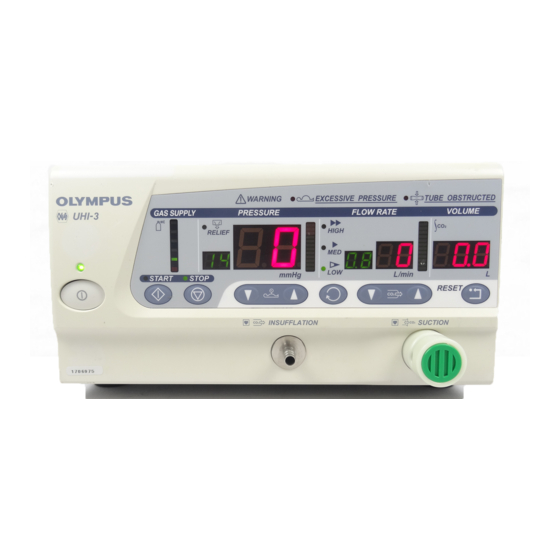
Chapter 2 Instrument Nomenclature Chapter 2 Instrument Nomenclature Symbols and descriptions Power switch Power ON/OFF INSUFFLATION connector SUCTION control pinch valve CYLINDER PRESSURE ABDOMINAL PRESSURE section Abdominal pressure Warning, excessive pressure Warning, tube obstructed Relief mode HIGH FLOW INSUFFLATION UNIT UHI-3... - Page 18 Chapter 2 Instrument Nomenclature FLOW RATE section Flow rate High mode Medium mode Low mode VOLUME section Total volume used Reset START STOP FOOTSWITCH connector GAS INLET HIGH FLOW INSUFFLATION UNIT UHI-3...
- Page 19 Chapter 2 Instrument Nomenclature Others Alternating current Circuit breaker Equipotential terminal Refer to instructions. HIGH FLOW INSUFFLATION UNIT UHI-3...
-
Page 20: Front Panel
2. Abdominal pressure 3. Flow mode selector control switches 4. Flow rate control switches 1. POWER switch 7. CO insufflation connector 5. RESET switch 9. START switch 8. STOP switch 6. CO suction control pinch valve HIGH FLOW INSUFFLATION UNIT UHI-3... - Page 21 8. STOP switch This switch is pressed to cancel the active mode 9. START switch When this switch is pressed, insufflation starts and the unit enters operation mode, in which smoke evacuation and automatic suction are performed. HIGH FLOW INSUFFLATION UNIT UHI-3...
- Page 22 15. Power indicator 9. Bar graph for flow rate 14. Lamp for start 10. Lamp for flow mode indication 13. Lamp for stop 12. Bar graph for supply pressure 11. Bar graph for abdominal pressure HIGH FLOW INSUFFLATION UNIT UHI-3...
- Page 23 14. Lamp for start This lamp lights when the START switch is pressed and indicates that the operating mode is active. 15. Power indicator This indicator lights when the power is ON. HIGH FLOW INSUFFLATION UNIT UHI-3...
-
Page 24: Rear Panel
These breakers prevent short circuiting. gas inlet Equipotential terminal In the case of equipotential, connect Connect the cylinder hose for UHI-3 this terminal to a potential (MAJ-1080) or medical gas pipeline equalization busbar of the electrical adaptor for UHI-3 (MAJ-1084/1085) installation. -
Page 25: Cylinder Hose (Pin) For Uhi-3 (Maj-1080)
Chapter 2 Instrument Nomenclature Cylinder hose (PIN) for UHI-3 (MAJ-1080) Hose Yoke This yoke connects the cylinder hose to the gas cylinder. Packing Connector Use the supplied wrench to connect to the CO gas inlet on the rear panel of the UHI-3. - Page 26 Chapter 2 Instrument Nomenclature MEDICAL GAS PIPELINE ADAPTOR (NIST) FOR UHI-3 (MAJ-1084) MEDICAL GAS PIPELINE ADAPTOR (DISS) FOR UHI-3 (MAJ-1085) Connector Connect the hose here for medical gas pipeline. Connector Use the supplied wrench to connect to the CO gas inlet on the rear panel of the UHI-3.
-
Page 27: Installation And Connection
Make sure that operation of the insufflator will take place in accordance with the precautions described in “Dangers, warnings and cautions” on page 6. Place the UHI-3 main unit on a level, stable work surface. HIGH FLOW INSUFFLATION UNIT UHI-3... -
Page 28: Connecting To An Ac Mains Supply
Confirm that the power is OFF. Connect the power cord plug directly to a 3-pin hospital grade AC outlet (wall mains outlet) which meets the power requirements indicated on the electrical rating plate on the rear of the UHI-3 (see Figure 3.1). Properly grounded wall... -
Page 29: Connecting A Co 2 Gas Cylinder
• Olympus is not liable for any injury or damage due to improper cylinder connection. • If a significant gas leak is noted from within the UHI-3, terminate its use immediately and contact Olympus. HIGH FLOW INSUFFLATION UNIT UHI-3... - Page 30 Chapter 3 Installation and Connection Remove the dust cap and plug from both ends of the cylinder hose for UHI-3 (MAJ-1080 only). Inspect the cylinder hose for UHI-3 for damage, cracks and other irregularities. Use the supplied wrench to attach the cylinder hose to the gas inlet on the rear panel of the UHI-3.
-
Page 31: Connecting The Medical Gas Pipeline Adaptor (Maj-1084/1085)
(MAJ-1084/1085) Using gases other than medical grade CO may result in fire, poisoning, complications, etc. In addition, oil, impurities, etc., may penetrate into the interior of the UHI-3 and impede proper CO gas insufflation. • Connect the gas supply hose to the UHI-3 before connecting it to the CO gas connector. -
Page 32: Connecting The Foot Switch (Mh-317)
Use the supplied wrench to attach the medical gas pipeline adaptor for UHI-3 to the CO gas inlet on the rear panel of the UHI-3. Tighten with a force of 24.5 N⋅m (2.5 kgf⋅m) (see Figure 3.2). Connect the adaptor to the hose for medical gas pipeline (see Figure 3.4). -
Page 33: Connecting The Insufflation Tube And Suction Tube
The type of filter is PALL OR01H (0.2 μm, hydrophobic) or equivalent filters; contact Olympus for further details. Even if the relief mode is not activated, Olympus highly recommends the use of a disposable filter. - Page 34 Insufflation tube (MH-397) can be used. However, it will supply a smaller quantity of gas than the MAJ-590. Insert the filter into the insufflation tube to this retention step. Figure 3.6 Filter connecting tube Filter Insufflation tube Luer-lock connector Figure 3.7 HIGH FLOW INSUFFLATION UNIT UHI-3...
- Page 35 If required, use the Y-shaped connector/extension tube to branch the suction (see Figure 3.9). Patient side Differential diameter connector Small luer-lock connector Y-shaped Small diameter tube connector Tube To other suction instrument To suction container Figure 3.9 HIGH FLOW INSUFFLATION UNIT UHI-3...
- Page 36 Insert the suction tube’s small diameter tube all the way into the groove of the CO suction control pinch valve on the front panel of the UHI-3 (see Figure 3.10). To prevent the tube from collapsing, there must be at least 10 cm between the differential diameter connector and the pinch valve groove (see Figure 3.11).
-
Page 37: Connecting The Electrosurgical Unit (Ues-40) Or The Sonosurg Generator (Sonosurg-G2)
(endoscope, light source, ancillary equipment, etc.). Attach the connectors of the aeration cable (MAJ-877) to the system connector of the UHI-3 and the system connector of the UES-40 or the system-A connector of the SonoSurg-G2. Then tighten the fixing screws on both connectors (see Figure 3.12). - Page 38 Chapter 3 Installation and Connection UHI-3 UES-40 Interactive cable (MAJ-877) UHI-3 SonoSurg-G2 Aeration cable (MAJ-877) Figure 3.12 HIGH FLOW INSUFFLATION UNIT UHI-3...
-
Page 39: Inspection
Before using this instrument for the first time, reprocess it according to the instructions given in Chapter 6, “Care, Storage and Disposal”. Inspection of the UHI-3 main unit Power supply Press the POWER switch to turn the unit ON. Confirm that all indicator lamps light and three tones sound. - Page 40 If the indicator drops down, gas is leaking. Check the connection of the cylinder hose again. If the indicator continues to move down, terminate operation and immediately contact Olympus. While the gas cylinder valve remains closed, set the insufflation mode to HIGH and press the START switch.
- Page 41 If the tube obstruction alarm does not sound, or if the excessive pressure alarm sounds, immediately stop using the insufflator and contact Olympus. Press the stop switch. Reset inspection Set the insufflation mode to LOW.
-
Page 42: Inspection Of The Cylinder Hose For Uhi-3
Chapter 4 Inspection Inspection of the cylinder hose for UHI-3 If the cylinder hose for UHI-3 is damaged, replace it with a new one. Inspect the cylinder hose for UHI-3 for scratches, cracks, or other damage. Inspect the packing inside the yoke for scratches, cracks or other damage. -
Page 43: Inspection Of The Insufflation Tube And Suction Tube
(e.g. blood) when the relief mode is activated, a disposable filter is necessary. The type of filter is PALL OR01H (0.2 μm, hydrophobic) or equivalent filters; contact Olympus for further details. Even if the relief mode is not activated, Olympus highly recommends the use of a disposable filter. -
Page 44: Inspection Of Uhi-3 Operation When Using A Veress Needle/Trocar
If the tube obstruction alarm or the excessive pressure alarm sounds, or if the abdominal pressure indication increases, the veress needle or trocar is damaged or not compatible with the UHI-3. Do not use incompatible veress needles or trocars. •... -
Page 45: Chapter 5 Operation
• If the UHI-3 unit is set to “insufflation” for a prolonged period of time without a CO insufflation connection, the decompressing devices may freeze. Under these conditions, operation of the UHI-3 unit, including insufflation, may be impossible. -
Page 46: Relief Mode
Chapter 5 Operation • Should blood, etc., back flow into the insufflation tube, make sure that it does not enter the UHI-3. Should any body fluids enter the UHI-3, immediately terminate its use and contact Olympus. • When a filter is used with the device, backward flow of body fluids (e.g. - Page 47 When relief mode is set to OFF: Gas release through the internal channel does not work. HIGH FLOW INSUFFLATION UNIT UHI-3...
-
Page 48: Inserting The Veress Needle
In addition, when the medical gas pipeline is connected, the actual gas flow rate may not conform to the figures in the table. HIGH FLOW INSUFFLATION UNIT UHI-3... - Page 49 Chapter 5 Operation To keep insufflation safer, the UHI-3 controls the gas flow during the first 25 seconds after the flow starts. Therefore, the actual flow rate of the gas might not reach the maximum flow rate for up to 25 seconds.
-
Page 50: Automatic Suction
We ask that the physicians make a suitable judgment from a professional standpoint. HIGH FLOW INSUFFLATION UNIT UHI-3... - Page 51 −300 mmHg. If the flow rate suction pressure is not between −500 to −300 mmHg automatic suction will not operate normally. • Always use suction tube (MAJ-591). Using any other tube will not only impair performance, but may lead to incorrect operation. HIGH FLOW INSUFFLATION UNIT UHI-3...
- Page 52 If the pressure is exceeded for 10 seconds or longer, automatic suction will be performed until the abdominal pressure drops to the set pressure. HIGH FLOW INSUFFLATION UNIT UHI-3...
-
Page 53: Smoke Evacuation (Optional Foot Switch [Mh-317] Required)
This table shows flow rate when low-flow-resistance instruments are connected to the insufflation tube. Accordingly, the actual gas flow rate may not conform exactly to the figures in the table. HIGH FLOW INSUFFLATION UNIT UHI-3... - Page 54 Connect the suction tube as outlined in Section 3.6, “Connecting the insufflation tube and suction tube”. Insert the connector of the foot switch (MH-317) into the foot switch connector on the UHI-3’s rear panel until a click is heard (see Figure 5.3). To disconnect, push this button while pulling outward.
-
Page 55: Automatic Exhaust
After the pedal is released, the exhaust function continues operating for about 5 seconds. When the UHI-3 is set to stop mode, its flow setting is LOW or abdominal pressure is below 3 mmHg, this function is disabled. -
Page 56: Resetting The Co Gas Volume Indicator
Close the gas cylinder valve (see Figure 5.4). Figure 5.4 Set the UHI-3 to insufflation mode and perform insufflation. After the UHI-3 enters the stop mode, turn the power switch OFF. Disconnect all tubes and the CO gas cylinder. Disconnect the power cord plug from the hospital grade AC outlet (wall mains outlet). - Page 57 Disconnecting the medical gas pipeline Set the UHI-3 to insufflation mode and perform insufflation. After the UHI-3 enters the stop mode, turn the power switch OFF. When the wall supply is connected, disconnect the hose on the facility side first.
-
Page 58: Chapter 6 Care, Storage And Disposal
All individuals responsible for reprocessing should thoroughly understand: • occupational health and safety regulations • all national and local hospital guidelines and policies • the instructions in this manual • the mechanical aspects of equipment • pertinent germicide labeling HIGH FLOW INSUFFLATION UNIT UHI-3... -
Page 59: Precautions
Store alcohol in an air-tight container. Alcohol stored in an open container is a fire hazard and will lose its efficacy due to evaporation. • The filter is a single-use device. Do not reuse. Discard the filter after each use. HIGH FLOW INSUFFLATION UNIT UHI-3... -
Page 60: Compatible Reprocessing Methods And Chemical Agents
Use a medical-grade, low-foaming, neutral pH detergent or enzymatic detergent and follow the manufacturer’s dilution and temperature recommendations. Contact Olympus for the names of specific brands that have been tested for compatibility with the insufflation tube, suction tube and luer-lock connectors. Do not reuse detergent solutions. -
Page 61: Cleaning Of The Uhi-3 Main Body, Foot Switch, Cylinder Hose And Medical Gas Pipeline Adaptor
Prevacuum 132 – 134°C (270 – 274°F) 5 minutes Table 6.1 Cleaning of the UHI-3 main body, foot switch, cylinder hose and medical gas pipeline adaptor • Set the power switch to OFF and disconnect the power cord before cleaning. -
Page 62: Storage Of The Uhi-3 Main Body, Foot Switch, Cylinder Hose And Medical Gas Pipeline Adaptor
Handle the equipment carefully; it can be damaged if dropped on a hard surface. Place the UHI-3 horizontally on a stable, level surface. Store the equipment at room temperature in a dry, well ventilated environment. Do not store in direct sunlight. -
Page 63: Sterilization Of The Insufflation Tube (Maj-590) And Suction Tube (Maj-591)
(MAJ-591) • Do not pinch the tubes and connectors when enclosing them in the package. • Ensure that the packaged tubes and connectors are not crushed by surrounding objects when placed in the autoclave. HIGH FLOW INSUFFLATION UNIT UHI-3... -
Page 64: Storage Of The Insufflation Tube (Maj-590), Suction Tube (Maj-591)
Store the sterile packages at room temperature in a clean, dry, well ventilated environment. Do not store in direct sunlight. Disposal When disposing of the UHI-3, or any of its components, follow all applicable national and local laws and guidelines. HIGH FLOW INSUFFLATION UNIT UHI-3... -
Page 65: Chapter 7 Troubleshooting
Chapter 7 Troubleshooting Chapter 7 Troubleshooting If the UHI-3 is visibly damaged, does not function as expected or is found to have other irregularities during the inspection described in Chapter 4, “Inspection”, do not use the UHI-3; contact Olympus. Some problems that appear to be malfunctions may be correctable by referring to Section 7.1, “Troubleshooting guide”. - Page 66 Turn the power on and wait 5 minutes or more before operating. The relief mode is The relief mode is set to OFF. Set the relief mode to ON. not performed. HIGH FLOW INSUFFLATION UNIT UHI-3...
- Page 67 The suction tube is collapsed. Correct the collapsed area. The suction tube is clogged. Remove foreign matters. The pinch valve is connected Connect it correctly. improperly. The foot switch is not connected. Connect the foot switch. HIGH FLOW INSUFFLATION UNIT UHI-3...
- Page 68 Remaining gas volume in gas Replace the gas cylinder continually sounds. cylinder is insufficient. with a new one. The cylinder hose for UHI-3 is not Connect hose correctly. connected. The hose for medical gas pipeline is Connect hose correctly. not connected.
-
Page 69: Alarm Functions
We ask that the physicians make a suitable judgment from a professional standpoint. HIGH FLOW INSUFFLATION UNIT UHI-3... - Page 70 In these conditions, the abdominal pressure cannot be measured, so immediately check the possible reasons and remedy as appropriate. • This warning is not performed during the STOP MODE. HIGH FLOW INSUFFLATION UNIT UHI-3...
-
Page 71: Returning The High Flow Insufflation Unit For Repair
Returning the high flow insufflation unit for repair Olympus is not liable for any injury or damage which occurs as a result of repairs attempted by non-Olympus personnel. Before returning the instrument for repair contact Olympus. With the instrument,... -
Page 72: Appendix
New products released after the introduction of this instrument may also be compatible for use in combination with instrument. For further details, contact Olympus. If combinations of equipment other than those shown below are used, the full responsibility is assumed by the medical treatment facility. - Page 73 Appendix Medical gas Medical gas pipeline adaptor for UHI-3 pipeline facility (MAJ-1084/1085) (optional) Hose for medical gas pipeline Cylinder hose for UHI-3 (MAJ-1080) (optional) Foot switch (MH-317) (optional) cylinder Insufflation tube High flow insufflation unit (UHI-3) (MAJ-590) Disposable filter Filter connecting...
- Page 74 Appendix Foot switch (MAJ-1259) Foot switch (MAJ-1258) Aeration cable (MAJ-877) High flow insufflation unit (UHI-3) Electrosurgical Unit (UES-40) SonoSurg-G foot switch (MAJ-51) Aeration cable (MAJ-877) High flow insufflution SonoSurg generator unit (UHI-3) (SonoSurg-G2) HIGH FLOW INSUFFLATION UNIT UHI-3...
-
Page 75: Specifications
Relative humidity 30 – 85% Atmospheric 700 – 1060 hPa pressure Storage − 25 to 70°C Storage environment Ambient temperature (− 13 to 158°F) Relative humidity 10 – 90% Atmospheric 700 – 1060 hPa pressure HIGH FLOW INSUFFLATION UNIT UHI-3... - Page 76 Specification Applicable gas • CO gas for medical use. • Connection to gas cylinder via the Olympus cylinder hose (PIN) for UHI-3 (MAJ-1080) • Connection to medical gas pipeline via the Olympus medical gas pipeline adaptor for UHI-3 (MAJ-1084 (NIST), MAJ-1085 (DISS)) •...
- Page 77 3 seconds. • Previous pressure setting is retained. Selected pressure setting is placed into memory. For safety reasons, settings at 21 mmHg or higher are memorized as 20 mmHg. HIGH FLOW INSUFFLATION UNIT UHI-3...
- Page 78 “HIGH” mode: 20 – 35 L/min settings modes: “MED” mode: 1.1 – 19 L/min “LOW” mode: 0.1 – 1.0 L/min Previous flow When power is turned ON, “LOW” mode is rate setting is selected. retained. HIGH FLOW INSUFFLATION UNIT UHI-3...
- Page 79 Frequency 50/60 Hz Input 150 VA Voltage Within ± 10% fluctuation Adjust to −400 to −300 mmHg. Suction pump Year of 1212345 manufacture The year of manufacture is the second digit of the serial number. HIGH FLOW INSUFFLATION UNIT UHI-3...
- Page 80 Protection against hazard IEC 60601-1 AP equipment of ignition Weight 2.1 kg 159.4 mm (W) × 184.7 mm (D) × 64.4 mm (H) Size Cylinder hose (PIN) for UHI-3 (MAJ-1080) Item Specification Hose length 1000 mm Compatible cylinder Pin-Index (ISO 407)
- Page 81 Appendix Medical gas pipeline adaptor (NIST) for UHI-3 (MAJ-1084) Medical gas pipeline adaptor (DISS) for UHI-3 (MAJ-1085) Item Specification Hose length 450 mm Compatible MAJ-1084 NIST (ISO 5359) connector MAJ-1085 DISS (ISO 5359) HIGH FLOW INSUFFLATION UNIT UHI-3...
- Page 83 ©2002 OLYMPUS MEDICAL SYSTEMS CORP. All rights reserved. No part of this publication may be reproduced or distributed without the express written permission of OLYMPUS MEDICAL SYSTEMS CORP. OLYMPUS is a registered trademark of OLYMPUS CORPORATION. Trademarks, product names, logos, or trade names used in this document are generally registered trademarks or trademarks of each company.
- Page 84 Manufactured by 2951 Ishikawa-cho, Hachioji-shi, Tokyo 192-8507, Japan Fax: (042)646-2429 Telephone: (042)642-2111 Distributed by 3500 Corporate Parkway, P.O. Box 610 Center Valley, PA 18034-0610, U.S.A. Fax: (484)896-7128 Telephone: (484)896-5000 5301 Blue Lagoon Drive, Suite 290 Miami, FL 33126-2097, U.S.A. Fax: (305)261-4421 Telephone: (305)266-2332 (Premises/Goods delivery) Wendenstrasse 14-18, 20097 Hamburg, Germany (Letters) Postfach 10 49 08, 20034 Hamburg, Germany Telephone: (040)237730 KeyMed House, Stock Road, Southend-on-Sea, Essex SS2 5QH, United Kingdom...
Need help?
Do you have a question about the UHI-3 and is the answer not in the manual?
Questions and answers