Table of Contents
Advertisement
Quick Links
NORDfire
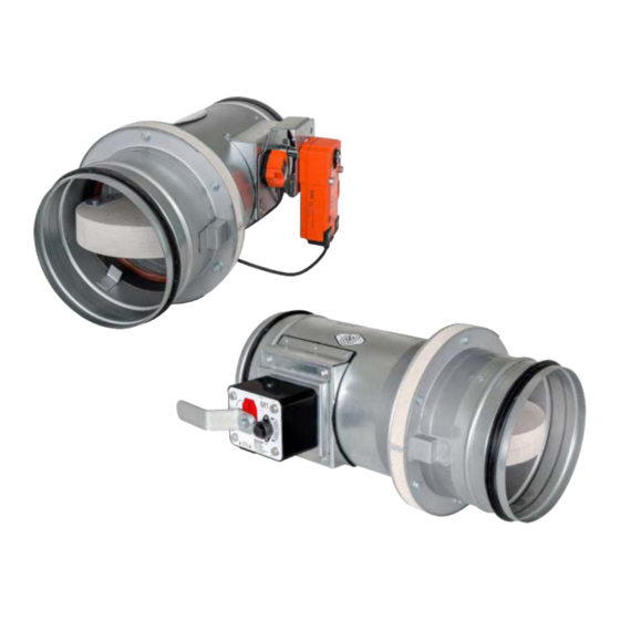
FDMA-PM Fire Damper
Round fire dampers ø900-1000
CE certified acc. to EN15650
Fire resistance up to EIS 120
External Casig leakage class C, Internal leakage class 2 acc. to EN 1751
Damper actuating mechanical, or electrical
Corrosion resistant according to EN 15650
Cycling test in class C 10 000 according to EN 15650
Maximum air speed through opened damper of 12 m/s and pressure difference
1200 Pa
Option for explosion hazard environments available
Advertisement
Table of Contents

Related Manuals for ETS NORD FDMA-PM Series

Summary of Contents for ETS NORD FDMA-PM Series
- Page 1 NORDfire FDMA-PM Fire Damper Round fire dampers ø900-1000 CE certified acc. to EN15650 Fire resistance up to EIS 120 External Casig leakage class C, Internal leakage class 2 acc. to EN 1751 Damper actuating mechanical, or electrical Corrosion resistant according to EN 15650 Cycling test in class C 10 000 according to EN 15650 Maximum air speed through opened damper of 12 m/s and pressure difference 1200 Pa...
-
Page 2: General Information
® NORDfire | FDMA-PM General information Description 1.1 Fire dampers are shutters in ducts of air-conditioning devices that prevent spreading the fire and combustion products from one fire segment to the other one by means of closing the duct in the points of fire separating constructions. - Page 3 ® NORDfire | FDMA-PM 1.3 Working conditions Right damper function is secured under the following conditions: Maximum air circulation speed: 12 m/s Maximum pressure difference: 1200 Pa The air circulation in the whole damper section must be secured as steady on whole surface.
- Page 4 ® NORDfire | FDMA-PM Design .80 Design .01 with mechanical control can be complemented with a terminal switches signaling of the damper blade position “CLOSED” and “OPEN”. Limit switches are connected via damper casing, cables are connected directly to limit switches. Fig.
- Page 5 ® NORDfire | FDMA-PM 2.2 Design with actuating mechanism Design .40, .50 The dampers are equipped with Belimo actuating mechanisms with back spring and thermoelec- tric actuating device, of range BF (hereinafter referred to only as the "actuating mechanism"). After being connected to power supply AC/DC 24V or AC 230V, respectively, the actuating mechanism moves the damper blade to "OPEN"...
- Page 6 ® NORDfire | FDMA-PM Tab 2.2.1. Actuating mechanism BELIMO BF 24-TN(-ST), BF 230-TN Actuating mechanism BELIMO BF 24-TN(-ST) BF 230-TN AC 24 V 50/60 Hz Nominal voltage AC 230 V 50/60 Hz DC 24 V Power consumption - motoring - holding Dimensioning 10 VA (Imax 8,3 A @ 5 ms) 12,5 VA (Imax 500 mA @ 5 ms)
- Page 7 ® NORDfire | FDMA-PM Fig. 11 Design with actuating mechanism Position: 1- Damper casing 2- Mechanics 3- Damper blade 4- Inspection hole covering 5- BAT thermoelectrical starting mechanism 6- Hole for camera 3.2 Weights and effective area Tab 3.2.1. Dampers SPIRO Weight Effective Actuating...
-
Page 8: Placement And Assembly
® NORDfire | FDMA-PM 3.3 Blades overlaps Tab 3.3.1. Blades overlaps Blades overlaps Dimension Overlaps Act. mechanism side "g" DAMPERS SPIRO Tab. 4.2.1 Fig.26 Side without act.mechanism "h" Act. mechanism side "e" DAMPERS WITH FLANGES Tab. 4.2.2 Fig.27 Side without act. mechanism "f"... - Page 9 ® NORDfire | FDMA-PM Fig. 13 The distance between the fire damper and the construction Fig. 14 Built in edge "Wall edge sticker" indicates the recommended edge of installation of fire damper into the fire partition structure (wall). The damper must be installed so that the entire damper blade - in the closed position - is located inside the fire separating structure (wall) and at the same time the control mechanism and inspection openings are freely accessible.
- Page 10 ® NORDfire | FDMA-PM Fig. 15 Installation opening Installation opening- round damper Installation opening- round damper Installation opening- round damper Weichschott system * For dampers with flanges is valid D + 160 mm 4.2 Examples of fire damper installing The fire damper can be integrated into a solid wall construction made e.g. of normal concrete/ masonry, porous concrete with minimum thickness 100 mm or into solid ceiling construction made e.g.
-
Page 11: Statement Of Installations
® NORDfire | FDMA-PM Statement of installations 5.1 Installation method list Tab 5.1.1.Installation method list Wall/Ceiling Fire Fire separating constru. Installation Page Min.thickness resist. [mm] EIS 120 Mortar or gypsum EIS 90 Battery - mortar or gypsum EIS 90 Installation next to wall - mortar or EIS 90 gypsum and mineral wool Solid wall construction... - Page 12 ® NORDfire | FDMA-PM 5.2 Installation in solid wall construction Fig. 16 Solid wall construction- mortar or gypsum EIS 120 EIS 90 Position: 1 Fire damper 2 Solid wall construction 3 Mortar or gypsum 4 Duct Shown schemes of incorporation and damper are illustrative only! www.etsnord.com RDT-43-0921...
- Page 13 ® NORDfire | FDMA-PM Fig. 17 Solid wall construction- battery- mortar or gypsum EIS 90 Position: Notice: • Installation opening for each damper has minimal dimensions 1 Fire damper • D+80 mm (D+160 mm for dampers with flanges) 2 Solid wall construction •...
- Page 14 ® NORDfire | FDMA-PM Fig. 18 Solid wall construction- installation next to wall, ceiling- mortar or gypsum and mineral wool EIS90 Position: 1 Fire damper 2 Mortar or gypsun 3 Stuffing box (mineral stone wool min. density 140 kg/m³) Notice: •...
- Page 15 ® NORDfire | FDMA-PM Fig. 20 Solid wall construction- stuffing box, fire protection mastic and cement lime plate EIS 90 Screws has to be fixed in wall/ceiling construction. (If it is needed use steel bracket). Position: 1 Fire damper 2 Solid wall construction 3 Stuffing box (mineral stone wool min.
- Page 16 ® NORDfire | FDMA-PM 5.3 Installation in solid ceiling construction Fig. 21 Outside solid wall construction- mineral wool- mortar or gypsum EIS 45 * Around the perimeter Position: 1 Fire damper 2 Solid wall construction 3 Mortar or gypsum 4 Stone wool with wired mat on one side, density 66 kg/m³ 5 Duct Used materials - example:** 4 Isover Ultimate Protect Wired MAT 4.0, th.
- Page 17 ® NORDfire | FDMA-PM Fig. 22 Outside solid ceiling construction- mineral wool- stuffing box and fire protection mastic EIS 45 * Around the perimeter Position: 1 Fire damper 2 Solid wall construction 3 Mineral stone wool min.density 150 kg/m³ 4 Fire protection mastic min.thickness 1 mm 5 Stone wool with wired mat on one side, density 66 kg/m³...
- Page 18 ® NORDfire | FDMA-PM Fig. 23 Outside solid ceiling construction- mineral wool- stuffing box, fire protection mastic and cement lime plate EIS 90 Screws has to be fixed in wall/ceiling construction. (If it is needed use steel bracket). Position: 1 Fire damper 2 Solid wall construction 3 Stuffing box (mineral stone wool min.
- Page 19 ® NORDfire | FDMA-PM 5.4 Installation in solid ceiling construction Fig. 24 Gypsum wall construction- mortar or gypsum EIS 120 EIS 90 Installation opening has to be reinforced by profile (UW, CW). Profil is fixed by screws ≥3,5 mm with corresponding length. Distance between screws ≤200 mm.
- Page 20 ® NORDfire | FDMA-PM Fig. 25 Gypsum wall construction- Battery- mortar or gypsum EIS 90 Installation opening has to be reinforced by profile (UW, CW). Profil is fixed by screws ≥3,5 mm with corresponding length. Distance between screws ≤200 mm. Installation opening has to be reinforced by profile (UW, CW).
- Page 21 ® NORDfire | FDMA-PM Fig. 26 Gypsum wall construction- installation next to wall, ceiling- mortar or gypsum and mineral wool EIS 90 Installation opening has to be reinforced by profile (UW, CW). Profil is fixed by screws ≥3,5 mm with corresponding length. Distance between screws ≤200 mm.
- Page 22 ® NORDfire | FDMA-PM Fig. 28 Gypsum wall construction- stuffing box, fire protection mastic and cement lime plate EIS 90 Installation opening has to be reinforced by profile (UW, CW). Profil is fixed by screws ≥3,5 mm with corresponding length. Distance between screws ≤200 mm.
- Page 23 ® NORDfire | FDMA-PM 5.5 Installation outside gypsum wall construction Fig. 29 Outside gypsum wall construction- mineral wool- mortar and gypsum EIS 45 Installation opening has to be reinforced by profile (UW, CW). Profil is fixed by screws ≥3,5 mm with corresponding length.
- Page 24 ® NORDfire | FDMA-PM Fig. 30 Outside gypsum wall construction- mineral wool- stuffing box and fire protection mastic EIS 90 Installation opening has to be reinforced by profile (UW, CW). Profil is fixed by screws ≥3,5 mm with corresponding length. Distance between screws ≤200 mm.
- Page 25 ® NORDfire | FDMA-PM Fig. 31 Outside gypsum wall construction- mineral wool- stuffing box and fire protection mastic and cement lime plate Installation opening has to be EIS90 reinforced by profile (UW, CW). Profil is fixed by screws ≥3,5 mm with corresponding length.
- Page 26 ® NORDfire | FDMA-PM 5.6 Installation in solid ceiling construction Fig. 32 Solid ceiling construction- mortar or gypsum EIS 120 EIS 90 * min. 110 - Concrete/ min. 125 - Aerated concrete Position: 1 Fire damper 2 Solid ceiling construction 3 Mortar or gypsum 4 Duct Shown schemes of incorporation and damper are illustrative only!
- Page 27 ® NORDfire | FDMA-PM Fig. 33 Solid ceiling construction- Battery- mortar or gypsum EIS 90 * min. 110 - Concrete/ min. 125 - Aerated concrete Position: 1 Fire damper 2 Solid ceiling construction 3 Mortar or gypsum Notice: • Installation opening for each damper has minimal dimensions D+80 mm (D+160 mm for dampers with flanges) •...
- Page 28 ® NORDfire | FDMA-PM Fig. 34 Solid ceiling construction- stuffing box, fire protection mastic and cement lime plate EIS 90 Screws has to be fixed in wall/ceiling construction. (If it is needed use steel bracket). * min. 110 - Concrete/ min. 125 - Aerated concrete Position: 1 Fire damper 2 Solid ceiling construction...
- Page 29 ® NORDfire | FDMA-PM Fig. 35 Solid ceiling construction- Weichschott EIS 90 * min. 110 - Concrete/ min. 125 - Aerated concrete Position: 1 Fire damper 2 Solid ceiling construction 3 Fire resistant board 4 Fire stop coating thickness 1 mm 5 Duct Used materials - example:* 3 Hilti CFS-CT B 1S 140/50...
- Page 30 ® NORDfire | FDMA-PM 5.7 Installation outside solid ceiling construction Fig. 36 Outside solid ceiling construction- mineral wool- mortar or gypsum EIS 90 * min. 110 - Concrete/ min. 125 - Aerated concrete Position: 1 Fire damper 2 Solid ceiling construction 3 Mortar or gypsum 4 Stone wool with one side stitched wire fencing (min.
- Page 31 ® NORDfire | FDMA-PM Fig. 37 Outside solid ceiling construction- concrete EIS 90 * min. 110 - Concrete/ min. 125 - Aerated concrete ** Around the perimeter Position: 1 Fire damper 2 Solid ceiling construction 3 Concrete B20 4 Rebar 5 Duct Shown schemes of incorporation and damper are illustrative only! Images are for illustrative purposes...
-
Page 32: Suspension System
® NORDfire | FDMA-PM Suspension system 6.1 Mounting to the ceiling wall Fig. 38 Mounting to the ceiling wall Load capacities of threaded hanger rods F [N] at the required resistance 90 minutes Position: Weigh G [kg] Size [mm²] 1 Threaded rod M8 – M20 for 1 piece for 1 pair 2 Nut... - Page 33 ® NORDfire | FDMA-PM 6.2 Horizontal installation Fire dampers can be suspended by using threaded rods and a mounting profiles. Load the suspension system depend on weight of the fire damper. Damper assembly procedures must be done so as all load transfer from the fire separating constructions to the damper body is absolutely excluded.
- Page 34 ® NORDfire | FDMA-PM 6.3 Vertical installation Fire dampers can be suspended by using threaded rods and a mounting profiles. Load the suspension system depend on weight of the fire damper. Damper can be suspended from the ceiling construction or supported above the ceiling con- struction.
- Page 35 ® NORDfire | FDMA-PM 6.4 Round fire damper suspension on the wall- horizontal installation Duct between fire damper and fire separating construction can be suspended by using threaded rods and suspension rings. Load the suspension system depend on weight of the fire damper and duct system.
-
Page 36: Technical Data
® NORDfire | FDMA-PM III. Technical data Pressure loss 7.1 Pressure loss calculation [Pa] pressure lost m.s ] air flow speed in nominal damper section air density [kg.m ] coefficient of local pressure loss for the nominal damper section (see Tab. 11.1.1.) 7.2 Determination of pressure loss by using diagram =1,2 kg m Diagram 7.2.1.Pressure losses for air density... -
Page 37: Coefficient Of Local Pressure Loss
® NORDfire | FDMA-PM Coefficient of local pressure loss (-) 8.1 Coefficient of local pressure loss Tab 8.1.1. Coefficient of local pressure loss 1000 0,090 0,083 Noise data 9.1 Level of acoustic output corrected with filter A. level of acoustic output corrected with filter A level of acoustic output related to the 1 m²... -
Page 38: Material, Finishing
® NORDfire | FDMA-PM Tab 9.3.2. Correction to the weight filter A [m/s] [dB] -15,0 -11,8 -9,8 -8,4 -7,3 -6,4 -5,7 -5,0 -4,5 -4,0 -3,6 Diagram 9.3.3.Relative level expressing the shape of the spectrum Lrel h [Hz] [m/s] 1000 2000 4000 8000 -4,5... -
Page 39: Inspection, Testing
® NORDfire | FDMA-PM The leaf of the damper is made from a single piece of homogeneous material Promatect-MST, thickness 40 mm. Plastic, rubber and silicon components, sealants, foaming bands, glass-ceramic seals, hous- ings, brass bearings of the leaf, servo drives, and end switches are identical for all material variants of the dampers. -
Page 40: Entry Into Service And Revisions
® NORDfire | FDMA-PM Fig. 42 Embedding/ fixing the damper Protecting the damper against buckling, above all when there are big diameters and sizes of fire dampers! WRONG! Brace with wooden blocks 13.3 To ensure reliable fire damper function it is necessary to avoid blocking the closing mechanism and contact surfaces with collected dust, fibre and sticky materials and solvents. -
Page 41: Spare Parts
® NORDfire | FDMA-PM • Mechanism dimension is marked M1 to M4, according to internal forces of spring. Adjustment of damper blade in position "OPEN" shall be made following: • Rotate control lever by 90°. • Lever get fasten automatically in “OPEN” position. •... - Page 42 ® NORDfire | FDMA-PM If installation holders, installation frame or design for installation in Weichschott system are requested, it has to be mentioned separately in the order. Installation frame could be fixed to the damper body or supplied separately. Tab 16.4.1.Dampers design Dampers design Additional digit Manual and thermal...
-
Page 43: Data Label
® NORDfire | FDMA-PM 17. Data label 17.1 Data label is placed on the damper body Images are for illustrative purposes RDT-43-0921 We reserve the right to make changes... - Page 44 ETS NORD AS Address: Peterburi tee 53 11415 Tallinn Estonia Phone: +372 680 7360 info@etsnord.ee www.etsnord.ee ETS NORD Finland Address: Pakkasraitti 4 04360 Tuusula Finland Phone: +358 0401 842 842 info@etsnord.fi www.etsnord.fi ETS NORD Sweden Address: Järsjögatan 7 69235 Kumla...
Need help?
Do you have a question about the FDMA-PM Series and is the answer not in the manual?
Questions and answers