Table of Contents
Advertisement
Quick Links
Advertisement
Table of Contents

Related Manuals for Partner K950 RING


Summary of Contents for Partner K950 RING
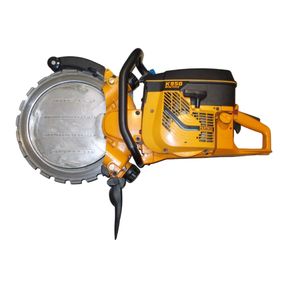
- Page 1 PARTNER K950 RING Workshop Manual...
-
Page 2: Table Of Contents
CONTENTS Page PARTNER 1. LITERATURE 2. BASIC FUNCTION K950 RING 3. COMPONENTS – ORIENTATION 4. REPLACEMENT OF CUTTER BLADE 5. ROLLERS – ADJUSTMENT/INSPECTION 6. ENGAGEMENT AND SUPPORT ROLLERS 7. REPLACEMENT OF ENGAGEMENT AND SUPPORT ROLLERS 8. REPLACEMENT OF THE ROLLERS’ BEARINGS 9. -
Page 3: Literature
Partner K950 Ring consists of two work- shop handbooks. Workshop manual K950 RING This encompasses measures that are specific to the K950 Ring, such as servicing of the blade’s drive and control systems. PARTNER PARTNER Workshop manual POWER CUTTERS... -
Page 4: Basic Function
BASIC FUNCTION The blade’s drive and control systems Eccentric drive The unique concept behind the K950 Ring is its eccentric drive (outside the centre) and control of the cutter blade (A). Function The drive disc (B) which is powered by a belt dri- ven off the engine, has a groove into which the blade slots. -
Page 5: Components - Orientation
NOTE Compared with the hydraulic ring cutter, the Partner K3600, the engagement and support rollers have switched places in the K950 Ring. The blade’s direction of rotation in relation to the machine is the same New version for both machines (dragging blade),... - Page 6 REPLACEMENT OF CUTTER BLADE Removal Removal Unscrew the knob to its end First unscrew the two knobs to their position. end positions – the drive disc now applies no tension at all on the Unscrew the adjustment blade. screws (A) at least two turns. Unscrew the adjustment screws (A) at Undo the lock-nuts (B).
-
Page 7: Replacement Of Cutter Blade
REPLACEMENT OF CUTTER BLADE Replacement of drive disc Blade and drive disc replaced together A new blade is always fitted together with a new driver disc. When fitting an already used blade, its respective drive disc should also be fitted. A used blade may be run together with a new drive disc, but a new blade may never be run together with a used drive disc. -
Page 8: Rollers - Adjustment/Inspection
ROLLERS – ADJUSTMENT/INSPECTION Correct adjustment The rollers must always be adjusted when: Correctly adjusted rollers are very important to the machine’s function and in order to reduce – switching to a new blade wear. – switching to another used blade –... -
Page 9: Engagement And Support Rollers
ENGAGEMENT AND SUPPORT ROLLERS Replaceable consumables The drive disc and the engagement Upper and lower rollers can and support rollers are subjected to switch places considerable wear owing to the slurry It is normal for the upper engage- in which they have to operate. These ment roller’s flange to wear more Min. - Page 10 REPLACEMENT OF ENGAGEMENT AND SUPPORT ROLLERS Grease – properties figure 3 indicates the grease’s Worn-out engagement rollers and sup- The grease used in the following NLGI rating. service measures should be of a If other brands are used, grease port rollers have a smaller diameter thick type that offers good with a corresponding NLGI rating than their new counterparts.
-
Page 11: Replacement Of Engagement And Support Rollers
REPLACEMENT OF ENGAGEMENT AND SUPPORT ROLLERS Remove the worn-out Remove the worn-out parts parts After removing the hex-head screw, Lift off the engagement rol- take off the worn part. ler. Clean and grease the engagement Clean and grease the roller’s seat. (The grease prevents engagement roller’s seat. - Page 12 REPLACEMENT OF ENGAGEMENT AND SUPPORT ROLLERS Support rollers Support rollers Inspection Inspection Check that the support roller’s Check that the support roller’s bear- bearings are undamaged. ings are undamaged – the roller Check that the bearing arm should be able to rotate freely, with can move and that there is smooth movement and without play.
-
Page 13: Replacement Of The Rollers' Bearings
REPLACEMENT OF THE ROLLERS’ BEARINGS Tools Tools Tool 506 38 85-01 Tool 506 38 85-01 Used for removing and fit- The bearing tool, with an installation ting the rollers’ bearings. and removal sleeve, is used for The inner diameter of the removing and fitting of bearings for rotating handle is tailored the engagement and support rollers. - Page 14 REPLACEMENT OF THE ROLLERS’ BEARINGS Fit new bearings Fit new bearings 1. Place the shaft with the 1. Place the shaft with the screw screw head in the hole on head in the hole on the bearing tool. the bearing tool. Press in the Insert a ball-bearing and place the bearing until the mandrel mandrel on the shaft.
- Page 15 REPLACEMENT OF THE ROLLERS’ BEARINGS Remove bearing units Remove bearing units Place the removal sleeve with Secure the bearing tool in a vice. its face upward and turn the bearing arm so that the tool’s Place the removal sleeve with its face sleeve meets the bearing upward and turn the bearing arm so arm’s screw.
- Page 16 In order to be able to replace the using tool 506 37 53-01. bearing sleeve, it is necessary to use a special tool produced by Partner. The tool’s part number is 506 37 53-01. For removal, use the complete tool as in the illustration.
-
Page 17: Replacement Of Drive Disc Bearing
In order to replace the drive disc bear- ring using tool 506 37 61-01. ing, it is necessary to use a special tool produced by Partner. The tool’s part number is 506 37 61-01. The tool is used both for removal and for installation of the drive disc bearing. - Page 18 REPLACEMENT OF DRIVE DISC BEARING Drive disc Drive disc Press in the rotation catch Press in the rotation catch and and remove the drive disc. remove the centre screw. Remove the flange washer and the drive disc. Companion flange Companion flange Lift off the drive disc’s com- Lift off the drive disc’s companion panion flange.
- Page 19 REPLACEMENT OF DRIVE DISC BEARING Fit bearing Fit bearing Do the following with the Do the following with the machine transmission side facing on a flat surface. The transmission upward. side should face upward and the underside should be accessible. Fit inner bearing Fit inner bearing Place the bearing on the tool...
- Page 20 108 89 37-26 English...
Need help?
Do you have a question about the K950 RING and is the answer not in the manual?
Questions and answers