Table of Contents
Advertisement
Vespa would like to thank you
for choosing one of its products. We have prepared this manual to help you to get the very best from your vehicle. Please read it carefully before riding
the vehicle for the first time. It contains information, tips and precautions for using your vehicle It also describes features, details and devices to assure
you that you have made the right choice. We believe that if you follow our suggestions, you will soon get to know your new vehicle well and that it will
continue to give you satisfactory service for many years to come. This booklet forms an integral part of the vehicle; should the vehicle be sold, it must
be transferred to the new owner.
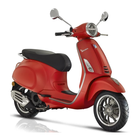
Vespa Primavera S - Sprint S 125-150
Ed. 01_05/2018 Cod. 1Q000662 (IT-FR-DE-ES-NL-EN-PT-EL)
Advertisement
Table of Contents


Need help?
Do you have a question about the Primavera S and is the answer not in the manual?
Questions and answers