
Related Manuals for Omcan G1.2YBM2F


Summary of Contents for Omcan G1.2YBM2F
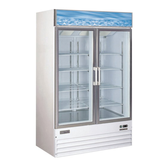
- Page 1 Glass Door Merchandisers Instruction Manual Version 4.1 3115 Pepper Mill Court, Mississauga, ON, L5L 4X5 1-800-465-0234 4450 Witmer Industrial Estates, Unit 4, Niagara Falls, NY, 14305 www.omcan.com...
-
Page 2: Table Of Contents
Table of Contents Model G1.2YBM2F / Model G258BMF / Model G368BMF Model D648BM2F / Model D768BM2F † Section Page General Information -------------------------------------------------------------------------------- 3 Installation -------------------------------------------------------------------------------------------- 3 Safety -------------------------------------------------------------------------------------------------- 3 Maintenance ----------------------------------------------------------------------------------------- 4 Troubleshooting -------------------------------------------------------------------------------- 4 - 5 French Instructions ---------------------------------------------------------------------------- 6 - 9... -
Page 3: General Information
General Information Omcan Manufacturing And Distributing Company Inc. and Food Machinery Of America, Inc. dba Omcan are not responsible for any harm or injury caused due to any person’s improper or negligent use of this equipment. The product shall only be operated by someone over the age of 18, of sound mind, and not under the influence of any drugs or alcohol, who has been trained in the correct operation of this machine, and is wearing authorized, proper safety clothing. -
Page 4: Maintenance
Maintenance • When loading the unit: - Be careful not to block the air duct located at the back and the fan on the ceiling of the unit with contents. - Blocking the air flow may cause decrease in performance. - For the best performance, maintain at least 4 inches of clearance between the contents and the air duct. • Set the shelves that come with the unit to fit your needs. • Temperature controller: - The controller is located at the right, front corner of the ceiling, or on the front bottom panel. - To adjust temperature please refer to the manual of temperature controller. • Do not leave the unit door open for long period of time. For the most efficient operation, close the door immediately after the use. Troubleshooting SYMPTOMS POSSIBLE CAUSE Compressor will not start Check if the power cord has been plugged in. Check for blown fuse. Poor Performance Move the unit from direct sun light, and avoid installing heating devices near the unit. Install the unit in a well ventilated place with minimum of 6” clearance in the back. Check the condenser, and clean if heavy dust is collected. Check to see if contents are blocking the air duct. Check to see if refrigerant charge is low. Make sure the door is completely closed. No Interior Light Turn off the light switch and turn it on again. Make sure the light is correctly inserted into the sockets. Check the light, and replace it if blown. Unit Noisy Make sure to install the unit on level surface. Make sure to maintain the minimum clearance of 6” from the wall. - Page 5 Troubleshooting Condensation on Cabinet and/or Floor Reduce the relatively humidity in the area where the unit is installed. Gasket on door or head section is not sealing properly. Repair or replace gasket as necessary. For service call 1-800-465-0234. *Only Model G1.2YBM2F is Energy Star Certified. Model D768BM2F requires a 20 Amp Type D Breaker. †...
-
Page 10: Controller Instructions
Controller Instructions Digital controller model: PJEZ for cooler Display and functions During normal operation, the controller displays the value of the probe set using parameter/4(=1 ambient probe, default, = 2 second probe, = 3 third probe).In addition, the display has LEDs that indicate the activation of the control functions (see Table 1),while the 3 buttons can be used to activate/deactivate some of the functions(see Table 2). LED’s and Associated Functions (Table 1) Icon Function Normal Operation Start Up Blink Compressor On Request Request Defrost Request Output On Output Off Alarm No Alarm Clock RTC fitted and enabled, at RTC not fitted or disabled, not ON if RTC least 1 time band set even 1 time band set fitted... - Page 11 Controller Instructions Table of Functions activated by the buttons - Models S, X, Y, C (Table 2) Button Normal Operation Start Up Pressing the Button Alone Pressed Together More than 3 sec: toggle ON/ Start/Stop ON/OFF continuous cycle Down More than 3 sec: start/stop Pressed For 1 sec. Defrost defrost together display Start parameter firmware reset procedure vers. code Set Mute - 1 sec.: display/set the set For 1 sec.
- Page 12 Controller Instructions • to display/set the values of the parameter displayed, press SET, then UP/DOWN and finally SET to confirm the changes (returning to the parameter menu). To save all the new values and exit the parameter menu, press SET for 3 s; To exit the menu without saving the changed values (exit by timeout) do not press any button for at least 60 s. Digital controller model: IR33 for freezer Signals on the display The blinking status indicates a request for activation that cannot be implemented until the end of the Corresponding delay times. Icon Function Blink Startup Compressor Compressor on Compressor off Request Fan on Fan off Request Defrost Defrost in progress Defrost not required Request Auxiliary Output AUX Auxiliary Output Anti-sweat heater function active AUX not active active Alarm Delayed external No alarm present Alarms in normal operation...
- Page 13 Controller Instructions Light Auxiliary output light Auxiliary output light Anti-sweat heater function active not active active Service No malfunction Malfunction (eg. EEPROM error or probe fault) HACCP HACCP function HACCP function HACCP alarm (HA and/or enabled HF) not enabled Continuous Enabled Not enabled Request Cycle Setting the set point (desired temperature value) To display or set the set point, proceed as follow: 1. press the “Set” button for more than 1 second to display the set point; 2. increase or decrease the value of the set point, using the “ ” and “ ” respectively, until reaching the desired value; 3. press the “Set” button again to confirm the new value, Alarms with manual reset The alarms with manual reset can be reset by pressing the “ ” and “ ” for more than 5 sec.
- Page 14 Controller Instructions Accessing the configuration parameter (type F) 1. Hold the “ ” button for more than 5 s (if there are active alarms, first mute the buzzer), the display will show the first modifiable “F” parameter. Modifying the parameters After having displayed the parameter, either type “C” or type “F”, proceed as follows: 1. Use the “ ” or “ ” buttons to scroll the parameters, until reaching the parameter to be modified; when scrolling the parameters, an icon is shown on the display that represents the category of the parameter. 2. Alternatively, press the “ ” button to display a menu that can be used to quickly access the family of parameters to be modified. 3. Scrolling the menu using the “ ” and “ ” buttons displays the codes of the various categories of parameter, accompanied by the corresponding icon on the display(if present). 4. Once having reached the desired category, press “Set” to go directly to the first parameter in the chosen category(if no parameter is visible, pressing the “Set” button will have no effect). 5. At this stage, modify the parameters or return to the “Category” menu, using the “ ” button. 6. Press “Set” to display the value associated with the parameter. 7. Increase or decrease the value using the “ ” or “ ” buttons respectively. 8. Press “Set” to temporarily save the new value and return to the display of the parameter. 9. Repeat the operation from point 1 or point 2. 10. If the parameter has sub-parameters, press “Set” to display the first sub-parameter. 11. Press the “ ” or “ ” button to display all the sub-parameters. 12. Press “Set” to display the associated value. 13. Increase or decrease the value using the “ ” or “ ” button respectively.
-
Page 15: Controller Instructions - French
Controller Instructions - French Panneau de commande du congélateur Affichage et fonctions Pendant le fonctionnement normal le contrôle affi che sur l’ écran la valeur de la sonde réglée au paramètre/4 (=1sonde air ambiant par défaut, =2 deuxième sonde, 3= troisième sonde). De plus sur l’ écran apparaissent les LED qui indiquent l’ activation des fonctions de contrôle (voir Tab. 1), alors que les trois touches permettent d’ activer/désactiver certaines fonctions (voir Tab. 2). LED et fonctions associées (Tab.1) Icone Fonction Fonctionnement Normale Start Up Blink Compresseur Accès Éteint Requis Ventilateur Accès Éteint Requis Defrost Accès Éteint Requis Sortie Accès Sortie Éteint Alarme Tous Aucune Alarme... - Page 16 Controller Instructions - French Tableau activation fonctions a l’aide des touches - mod. S, X, Y, C (Tab.2) Touche Fonctionnement Normale Start Up Simple pression de la touche Pression combinée Plus de 3 s: alterne phases Appuyées ensemble ON/OFF ON/OFF activent/désactivent cycle continu Down Plus de 3 s: active/désactive Appuyées Pendant Defrost defrost ensemble activent 1 s affiche procédure cod. vers. REINTIALISATION firmware param.
- Page 17 Controller Instructions - French 4. • pour afficher/modifi er les valeurs du paramètre affiché appuyer sur SET, ensuite sur UP/DOWN et enfin sur SET pour confirmer la modification (on retourne ainsi au menu des paramètres). Pour sauver définitivement toutes les valeurs modifiées et sortir du menu paramètres appuyer sur SET pendant 3 s; Pour sortir du menu sans sauver les valeurs modifiées (sortie time out) n’ appuyer sur aucun bouton pendant au moins 60s. Panneau de commande du congélateur Signalisations sur l’écran Le clingnotement indique une demande ne pouvant être effectuée tant que ne seront pas finies les temporisations en cours. Icône Fonction Clignotant Démarrage Compress. Compresseur allumé Compress. éteint Requis Ventilateur Ventilateur allumé Fan off Requis Dégivrage Dégivr. en cours Dégivr. non requis Requis Sortie auxiliaire AUX Sortie auxiliaire Active fonct. anti-sweat active AUX non active heater...
- Page 18 Controller Instructions - French Éclairage Sortie auxiliaire Sortie auxiliaire Active function anti-sweat heater Éclairge active Éclairge non active Assistance Aucun Dysfonctionn. (ex. erreur dysfonctionnement EEPROM our sondes en panne) HACCP Fonction habilité (HA Fonction non Alarme HACCP mémorisée et/ou HF) habilitée Cycle Cont. Fonction activée Fonction non Fonction requise activée Programmations du point de consigne (valeur de température désirée) Procéder de la façon suivante pour afficher ou programmer le point de consigne: 1. appuyer sur la touche “Set “ pendant plus d’une seconde pour afficher le point de consigne; 2. augmenter ou diminuer la valeur du point de consigne au moyen des touches “ ” et “ ” respectivement,jusqu’à atteindre la valeur désirée;...
- Page 19 Controller Instructions - French Accès aux paramètres de configuration (type F) 1. Appuyer sur la touche “ ” pendant plus de 5 s (en cas d’alarme éteindre l’avertisseur sonore), sur l’afficheur apparaît le premier paramètre “F” modifiable. Modification des paramètres Après avoir visualisé le paramètre,qu’il soit du type “C” ou du type “F”, continuer de la façon suivante: 1. Avec les touches “ ” o “ ” faire défiler les paramètres jusqu’à celui à modifier, le défilement est accompagné de l’allumage d’une icône sur l’afficheur qui représente la catégorie d’appartenance du paramètre. 2. Ou comme alternative, appuyer sur la touche “ ” pour visualiser un menu permettant de rejoindre rapidement la famille de paramètres à modifier. 3. En faisant défiler le menu avec les touches “ ” et “ ” sur l’écran s’affichent les codes des différentes catégories de paramètres (voir tab. Récapitulation paramètres de fonctionnement) accompagnés de l’allumage de l’icône correspondante sur l’afficheur (si présente). 4. Une fois atteinte la catégorie souhaitée appuyer sur “Set” pour se retrouver directement sur le premier paramètre de la catégorie choisie (si aucun paramètre n’est visible, la pression de la touche “Set” n’aura aucun effet). 5. À ce point, il est possible de continuer à consulter les paramètres ou de retourner au menu “Catégorie” avec la touche “ ”. 6. Appuyer sur “Set” pour visualiser la valeur associée au paramètre. 7. Incrémenter ou décrémenter la valeur respectivement avec les touches “ ” ou “ ” 8. Appuyer sur “Set” pour mémoriser temporairement la nouvelle valeur et retourner à la visualisation du paramètre.
- Page 20 Controller Instructions - French Réglage de la Température OFF: température à laquelle le thermostat arrête le compresseur. 1→7: plus froid. ATTENTION: Reglage de la commande de temperature a la position la plus froide peut geler la bobine de l’evaporateur. Ce qui finira à auoir une temperature plus chaude à l’interieur.
-
Page 21: Parts Breakdown
Parts Breakdown Model G1.2YBM2F 24272... - Page 22 Parts Breakdown Model G1.2YBM2F 24272 No. Description No. Description No. Description Condenser Evaporator Door Wheel Rear Castor Mounting Plate Right Cover of Evaporator Heater of Inside Water Tray Link Plate of Castor Mounting Front Castor Mounting Plate Evaporator Fan Motor...
- Page 23 Parts Breakdown Model G258BMF 27952...
- Page 24 Parts Breakdown Model G258BMF 27952 No. Description No. Description No. Description Track of Compressor Mount- Cabinet Filter ing Plate Screw Feet Compressor Mounting Plate Condenser Digital Thermostat Exterior Water Tray Evaporator Light Switch Evaporator Fan Cover Shelf Power Switch Evaporator Cover K Clip Control Panel Evaporator Fan Motor...
- Page 25 Parts Breakdown Model G368BMF 24271...
- Page 26 Parts Breakdown Model G368BMF 24271 No. Description No. Description No. Description K Clip Fan Net Cover Screw Foot Shelf Screw Link Bar K Clip Hanging Bar Condenser Fan Motor Lamp Holder Cabinet Screw Cap Lamp Installing Panel Top Cover Hinge Screw Top Strengthen Frame Condenser Gasket...
- Page 27 Parts Breakdown Model D648BM2F 27951...
- Page 28 Parts Breakdown Model D648BM2F 27951 No. Description No. Description No. Description Junction Panel of Castor Fluorescent Light Condenser Fan Cover Mounting Plate Castor Mounting Plate Upper Hinge Condenser Fan Castor Cover of Copper Pipe Capillary Tube Control Panel LED Light Filter Door Seal Cover of LED Light...
- Page 29 Parts Breakdown Model D768BM2F 24273...
- Page 30 Parts Breakdown Model D768BM2F 24273 No. Description No. Description No. Description Back Cover Door Switch Wire Protector Drain-Water Hose Down Hinge Cover of Wire Box Caster Down Hinge Axis LED Light Exterior Water-Tray Axis Cover Return Pipe Cover Compressor Door Interior Water Tray Heater Dry Filter Door Gasket...
-
Page 31: Electrical Schematics
Electrical Schematics... - Page 32 Electrical Schematics...
- Page 33 Electrical Schematics...
-
Page 35: Warranty Registration
1889 Maryland Avenue, Mississauga, Ontario Niagara Falls, New York Canada, L5L 4X5 USA, 14305 Purchaser’s Information Name: Company Name: Address: Telephone: City: Province or State: Postal or Zip: Email Address: Country: Type of Company: Restaurant Bakery Deli Dealer from which Purchased: Butcher Supermarket Caterer Dealer City: Dealer Province or State: Institution (specify): Invoice: Other (specify): Model Name: Model Number: Serial Number: Machine Description: Date of Purchase (MM/DD/YYYY): Date of Installation (MM/DD/YYYY): Thank you for choosing Omcan... - Page 36 Over the last 60 years, Omcan has grown to become a leading supplier to the food service industry in Canada and the USA. Our success over these many years is directly attributed to our established relationships with all of our valued customers and through providing them with Diverse, Dependable and Proven products.
Need help?
Do you have a question about the G1.2YBM2F and is the answer not in the manual?
Questions and answers