
Subscribe to Our Youtube Channel
Related Manuals for Mighty Mule R4222


Summary of Contents for Mighty Mule R4222
- Page 1 PHOTO BEAM R4222 THROUGH BEAM Mighty Mule, Linear and GTO are registered trademarks of Nortek Security & Control LLC. www.nortekcontrol.com Technical Support: (800) 421-1587...
-
Page 2: Table Of Contents
Mounting and Connections . . . . . . . . . . . . . . . . . . . . . . . . . . . . . . . . . . . . . . . . . . 5 Wiring the R4222 Photo Eyes to Gate Operators......7 Transmitter Terminal . -
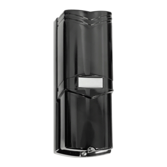
Page 3: Photoelectric Dual Beam Detector
PHOTOELECTRIC DUAL BEAM DETECTOR Parts Internal View Cover Wiring Knockout Connection Terminals Signal Level Display Indicator Tamper Lens Vertical Alignment Screw Cover Locking Screw Receiver Wiring Terminals Transmitter Wiring Terminals ... -
Page 4: Mounting Cautions
MOUNTING CAUTIONS Do not mount the detector in the following conditions: Where obstructions (plants, Where the mounting Where sunlight and headlights fences, etc.) are between the surface is unstable. shine directly into the front of receiver and the sender. the receiver. -
Page 5: Mounting And Connections
MOUNTING AND CONNECTIONS 1. Loosen the cover holding screw, and remove the outer cover. 2. Remove the rubber knock out, and use the screw holes to mount the unit. Wiring Back Cover 3. Remove the rubber knock-out, and pull the wire through. - Page 6 5. Connect wires to the terminals: See wiring diagram, next page. • Wire with 22awg minimum Correct Wrong Wrong • 300 ft (91 .4m) max length • Be sure to capture the wire ends under the wire clamp plates. • Avoid frayed ends on wires that might produce a short circuit.
-
Page 7: Wiring The R4222 Photo Eyes To Gate Operators
Wiring the R4222 Photo Eyes to Gate Operators Compatible with Mighty Mule Gate Openers 1. Connect the ( ) Terminals of the TRANSMITTER and RECEIVER to the POSITIVE terminal of battery with wire. 2. Connect the ( ) Terminals of the TRANSMITTER and RECEIVER to the NEGATIVE terminal of battery with wire. -
Page 8: Pole Mounting
Pole Mounting 1. Break out the wire hole on the bracket then pull out the wires. 2. Remove the cover. 3. Attach the base plate on the bracket using the Regular Ring. DIP SETTING NOTE: 1. DIP 1 & 2 on Transmitter & Receiver must be on the same position (same channel). 2. -
Page 9: Beam Alignment
BEAM ALIGNMENT 1. Remove the cover, and turn ON power. 2. Adjust the horizontal pivot, and the vertical adjustment screw using the built-in viewer. 3. Look through the peep hole on either side and adjust to put the opposite sensor in the middle of the cross-hairs in the viewfinder. -
Page 10: Beam Interruption Time Adjustment
BEAM INTERRUPTION TIME ADJUSTMENT VERIFY CORRECT OPERATION After installation, confirm correct operation by suitable walking. Condition Indication Transmitter Transmitting Greed LED is ON Beam Clear GOOD-LEVEL Indication Receiver Beam Blocked Alarm indication lamp is ON... -
Page 11: Troubleshooting
5. Adjust the optical axis. 4. The receiver or transmitter is unstable. 6. Adjust interruption time or change 5. Blocked by other moving objects. installation position. SPECIFICATIONS Model R4222 Detection Method Infrared photoelectric Outdoor 98.4 ft (30m) Range Indoor 295.2 ft (90m) - Page 12 • www.linear-solutions.com • www.mightymule.com ©2021 Nortek Security & Control LLC. All rights reserved. Mighty Mule, Linear and GTO are registered trademarks of Nortek Security & Control LLC. Nortek Security & Control LLC. 5919 Sea Otter Place, Suite 100, Carlsbad, CA 92010 USA...
Need help?
Do you have a question about the R4222 and is the answer not in the manual?
Questions and answers