
Related Manuals for mATX AIMB-763 Series

Summary of Contents for mATX AIMB-763 Series
- Page 1 AIMB-763 Series ® ® ® Intel Pentium D / Pentium ® Celeron / Core 2 Duo ATX Main Board User Manual...
- Page 2 Notices Federal Communications Commission Statement This device complies with Part 15 of the FCC Rules. Operation is subject to the following two conditions: • This device may not cause harmful interference, and • This device must accept any interference received including inter- ference that may cause undesired operation.
- Page 3 Safety information Electrical safety • To prevent electrical shock hazard, disconnect the power cable from the electrical outlet before relocating the system. • When adding or removing devices to or from the system, ensure that the power cables for the devices are unplugged before the sig- nal cables are connected.
- Page 4 About this guide This user guide contains the information you need when installing and configuring the motherboard. How this guide is organized This manual contains the following parts: • Chapter 1: Product introduction This chapter describes the features of the motherboard and the new technology it supports.
- Page 5 Typography Bold text Indicates a menu or an item to select Italics Used to emphasize a word or a phrase <Key> Keys enclosed in the less-than and greater- than sign means that you must press the enclosed key Example: <Enter> means that you must press the Enter or Return key <Key1>+<Key2>+<Key3>...
- Page 6 AIMB-763 User Manual...
-
Page 7: Table Of Contents
Contents Chapter 1 Product Introduction ........2 Welcome................2 Package contents ............... 2 Special features ..............3 1.3.1 Product highlights ............3 Before you proceed ............6 Figure 1.1 Onboard LED ........... 7 Motherboard overview ............8 1.5.1 Placement direction............8 1.5.2 Screw holes .............. - Page 8 1.7.2 Memory configurations..........23 1.7.3 DDR2 Qualified Vendors List ........23 Table 1.2 DDR2 533 Qualified Vendors List..24 1.7.4 Installing a DIMM ............25 Figure 1.20 Insatll a DIMM ........25 1.7.5 Removing a DIMM............26 Figure 1.21 Remove a DIMM........26 Expansion slots..............
- Page 9 2.1.1 CMOS RAM Auto-backup and Restore ....... 46 Entering Setup ..............47 Figure 2.1 Award BIOS Setup initial screen.... 47 Standard CMOS Setup ............ 48 2.3.1 Date................48 2.3.2 Time ................48 2.3.3 IDE channel 0/1 Master/Slave ........48 2.3.4 Drive A / Drive B............
- Page 10 2.5.13 DVMT/Fixed Memory Size.......... 55 Integrated Peripherals............56 Figure 2.5 Integrated peripherals ......56 Figure 2.6 On-Chip IDE Device ......56 2.6.1 IDE HDD Block Mode ..........57 2.6.2 IDE DMA Transfer Access........... 57 2.6.3 On-Chip IDE Device ............ 57 2.6.4 On-Chip Serial ATA.............
- Page 11 2.7.11 Soft-Off by PWR-BTTN ..........63 2.7.12 Wake-Up by PCI card........... 63 2.7.13 PowerOn by Ring............63 2.7.14 USB KB Wake-Up From S3......... 63 2.7.15 Resume by Alarm ............63 2.7.16 Primary IDE 0 (1) and Secondary IDE 0 (1) ....63 2.7.17 FDD, COM, LPT PORT ..........
- Page 12 AIMB-763 User Manual...
- Page 13 Product Introduction This chapter describes the mother- board features and the new technolo- gies it supports. Sections include: • Welcome • Package features • Special features • Before you proceed • Motherboard overview • Central Processing Unit (CPU) • System memory •...
-
Page 14: Chapter 1 Product Introduction
Chapter 1 Product Introduction This chapter describes the motherboard features and the new technologies it supports. 1.1 Welcome ® Thank you for buying an Advantech AIMB-763 motherboard! The motherboard delivers a host of new features and latest technologies, making it another standout in the long line of quality motherboards! Before you start installing the motherboard and hardware devices on it, check the items in your package with the list below. -
Page 15: Special Features
1.3 Special features 1.3.1 Product highlights Latest processor technology The motherboard comes with a 775-pin surface mount Land Grid Array ® ® ® ® (LGA) socket designed for the Intel Pentium D, Pentium 4, Celeron or Core 2 Duo processor in the 775-land package. The motherboard ®... - Page 16 ® Intel Viiv Technology support ® Intel Viiv Technology transforms your PC into an entertainment cen- ter, allowing you to enjoy and share digital multi-media content like ® never before. With Intel Viiv Technology-based computers, you can record, playback, organize, and edit digital media content easily. Enjoy the entertainment experience even more with sharp graphics, flawless video playback, and support for up to 7.1 channel surround sound.
- Page 17 Serial ATA technology The motherboard supports the Serial ATA technology through the Serial ® ATA interfaces and the Intel ICH7 DH chipset. The SATA specification allows for thinner, more flexible cables with lower pin count, reduced voltage requirement, and up to 300 MB/s data transfer rate. 8-channel high definition audio ®...
-
Page 18: Before You Proceed
1.4 Before you proceed Take note of the following precautions before you install motherboard components or change any motherboard settings. Caution! • Unplug the power cord from the wall socket before touching any compo- nent. • Use a grounded wrist strap or touch a safely grounded object or a metal object, such as the power supply case, before handling components to avoid... - Page 19 Onboard LED The motherboard comes with a standby power LED that lights up to indi- cate that the system is ON, in sleep mode, or in soft-off mode. This is a reminder that you should shut down the system and unplug the power cable before removing or plugging in any otherboard component.
-
Page 20: Motherboard Overview
1.5 Motherboard overview Before you install the motherboard, study the configuration of your chas- sis to ensure that the motherboard fits into it. Warning! Make sure to unplug the power cord before installing or removing the motherboard. Failure to do so can cause you physical injury and dam- age motherboard components. -
Page 21: Aimb-763G2 Motherboard Layout
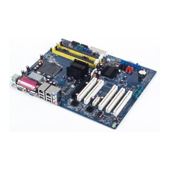
1.5.3 AIMB-763G2 Motherboard layout Figure 1.3: AIMB-763G2 Motherboard layout Chapter 1 Product Introduction... -
Page 22: Aimb-763Vg Motherboard Layout
1.5.4 AIMB-763VG Motherboard layout Figure 1.4: AIMB-763VG Motherboard layout AIMB-763 User Manual... -
Page 23: Central Processing Unit (Cpu)
1.6 Central Processing Unit (CPU) The motherboard comes with a surface mount LGA775 socket designed ® ® ® ® for the Intel Pentium D / Pentium 4 / Celeron / Core 2 Duo pro- cessor in the 775-land package. Caution! ®... -
Page 24: Installing The Cpu
1.6.1 Installing the CPU To install a CPU: Locate the CPU socket on the motherboard. Figure 1.5: Locate the CPU socket on the motherboard Notes Before installing the CPU, make sure that the socket box is facing towards you and the load lever is on your left. Press the load lever with your thumb (A) and move it to the left (B) until it is released from the retention tab. - Page 25 Lift the load lever in the direction of the arrow to a 135° angle. Figure 1.7: Lift the load lever Lift the load plate with your thumb and forefinger to a 100° angle (A), then push the PnP cap from the load plate window to remove (B).
- Page 26 Position the CPU over the socket, making sure that the gold trian- gle is on the bottom-left corner of the socket. The socket alignment key should fit into the CPU notch. Alignment key Gold triangle mark Figure 1.9: Position the CPU over the socket Close the load plate (A), then push the load lever (B) until it snaps into the retention tab.
- Page 27 Caution! The CPU fits in only one correct orientation. DO NOT force the CPU into the socket to prevent bending the connectors on the socket and dam- aging the CPU! Notes ® ® ® ® This motherboard supports Intel Pentium D or Intel Pentium ®...
-
Page 28: Installing The Cpu Heatsink And Fan
1.6.2 Installing the CPU heatsink and fan ® ® ® ® The Intel Pentium D / Pentium 4 / Celeron / Core 2 Duo LGA775 processor requires a specially designed heatsink and fan assembly to ensure optimum thermal condition and performance. Notes –... - Page 29 Fastener Motherboard hole Figure 1.11: Place the heatsink on top of the installed CPU Notes Make sure each fastener is oriented as shown, with the narrow groove directed outward. Push down two fasteners at a time in a diagonal sequence to secure the heatsink and fan assembly in place.
- Page 30 When the fan and heatsink assembly is in place, connect the CPU fan cable to the connector on the motherboard labeled CPU_FAN. Figure 1.13: Connect the fan cable Notes Do not forget to connect the CPU fan connector! Hardware moni- toring errors can occur if you fail to plug this connector.
-
Page 31: Uninstalling The Cpu Heatsink And Fan
1.6.3 Uninstalling the CPU heatsink and fan To uninstall the CPU heatsink and fan: Disconnect the CPU fan cable from the connector on the mother- board. Rotate each fastener counterclockwise. Figure 1.14: Rotate each fastener counterclockwise Pull up two fasteners at a time in a diagonal sequence to disengage the heatsink and fan assembly from the motherboard. - Page 32 Remove the heatsink and fan assembly from the motherboard. Figure 1.16: emove the heatsink and fan assembly Rotate each fastener clockwise to reset the orientation. Figure 1.17: Rotate each fastener clockwise AIMB-763 User Manual...
- Page 33 Notes The narrow end of the groove should point outward after resetting. (The photo shows the groove shaded for emphasis.) Narrow end of the groove Figure 1.18: Narrow end of the groove Chapter 1 Product Introduction...
-
Page 34: System Memory
1.7 System memory 1.7.1 Overview The motherboard comes with four Double Data Rate 2 (DDR2) Dual Inline Memory Modules (DIMM) sockets. A DDR2 module has the same physical dimensions as a DDR DIMM but has a 240-pin footprint compared to the 184-pin DDR DIMM. DDR2 DIMMs are notched differently to prevent installation on a DDR DIMM socket. -
Page 35: Memory Configurations
1.7.2 Memory configurations You may install 64 MB, 128 MB, 256 MB, 512 MB and 1 GB unbuffered ECC or non-ECC DDR DIMMs into the DIMM sockets using the mem- ory configurations in this section. Notes – IF you installed four 1GB memory modules, the system may detect less than 3GB of total memory because of address space allocation for other critical functions. -
Page 36: Ddr2 533 Qualified Vendors List
Table 1.2: DDR2 533 Qualified Vendors List DIMM support Size Vendor Model Brand Side(s) Component A B C 512MB Samsung M378T6553BG0-CD5 K4T51083QB-GCD5 V V V 256MB Samsung M378T3253FG0-CD5 K4T56083QF-GCD5 V V V 512MB Samsung M378T6453FG0-CD5 K4T56083QF-GCD5 V V V 512MB Infineon HYS64T64000GU-3.7-A Infineon SS HYB18T512800AC37... -
Page 37: Installing A Dimm
1.7.4 Installing a DIMM Caution! Unplug the power supply before adding or removing DIMMs or other system components. Failure to do so can cause severe damage to both the motherboard and the components. To install a DIMM: Unlock a DIMM socket by pressing the retaining clips outward. Align a DIMM on the socket such that the notch on the DIMM matches the break on the socket. -
Page 38: Removing A Dimm
1.7.5 Removing a DIMM Follow these steps to remove a DIMM. Simultaneously press the retaining clips outward to unlock the DIMM. Notes Support the DIMM lightly with your fingers when pressing the retaining clips. The DIMM might get damaged when it flips out with extra force. -
Page 39: Expansion Slots
1.8 Expansion slots In the future, you may need to install expansion cards. The following sub- sections describe the slots and the expansion cards that they support. Warning! Make sure to unplug the power cord before add- ing or removing expansion cards. Failure to do so may cause you physical injury and damage motherboard components. -
Page 40: Pci Slots
1.8.3 PCI slots The PCI slots support cards such as a LAN card, SCSI card, USB card, and other cards that comply with PCI specifications. The figure shows a LAN card installed on a PCI slot. Figure 1.22: A LAN card installed on a PCI slot 1.8.4 PCI Express x 16 This motherboard supports one PCI Express x 16 graphics card. -
Page 41: Pci Express X 1
1.8.5 PCI Express x 1 This mother board supports PCI Express x1 network cards, SCSI cards and other cards that comply with the PCI Express specifications. The fig- ure shows the type of net work card that can be installed on the PCI Express x1 slot. -
Page 42: Jumpers
1.9 Jumpers Clear RTC RAM (CLRTC) This jumper allows you to clear the Real Time Clock (RTC) RAM in CMOS. You can clear the CMOS memory of date, time, and sys- tem setup parameters by erasing the CMOS RTC RAM data. The onboard button cell battery powers the RAM data in CMOS, which include system setup information such as system passwords. - Page 43 Figure 1.25: Clear RTC RAM Notes You do not need to clear the RTC when the system hangs due to overclocking. For system failure due to overclocking, use the C.P.R. (CPU Parameter Recall) feature. Shut down and reboot the system so the BIOS can automatically reset parameter settings to default values.
-
Page 44: Connectors
1.10 Connectors 1.10.1 AIMB-763G2 Rear panel connectors Figure 1.26: AIMB-763G2 Rear panel connectors 1.10.2 AIMB-763VG Rear panel connectors Figure 1.27: AIMB-763VG Rear panel connectors PS/2 mouse port (green). This port is for a PS/2 mouse. Parallel port. This 25-pin port connects a parallel printer, a scanner, or other devices. -
Page 45: Lan Port Led Indications
Table 1.3: LAN port LED indications ACT/LINK LED SPEED LED Status Description Status Description No link 10 Mbps connection GREEN Linked ORANGE 100 Mbps connection BLINKING Data activity GREEN 1 Gbps connection ACT/LINK SPEED LAN port Figure 1.28: LAN (RJ-45) Port Line In port (light blue). -
Page 46: Internal Connectors
1.10.3 Internal connectors Floppy disk drive connector (34-1 pin FLOPPY) This connector is for the provided floppy disk drive (FDD) signal cable. Insert one end of the cable to this connector, then connect the other end to the signal connector at the back of the floppy disk drive. Notes Pin 5 on the connector is removed to prevent incorrect cable con- nection when using an FDD cable with a covered Pin 5. -
Page 47: Cable Select Mode
Cable Select Mode - user this mode to select the operating mode by cable connectors. Table 1.4: Cable Select Mode No. of drives Drive type Drive jumper Cable connector With OS Black With OS Cable select Black Without OS Gray Jumper Select Mode - use this mode to select the operating mode by hard disk drive jumper. - Page 48 Serial ATA connectors (7-pin SATA1, SATA2, SATA3, SATA4) These connectors are for the Serial ATA signal cables for Serial ATA hard disk drives. Figure 1.31: SATA connectors Notes ® ® Install the Windows 2000 Service Pack 4 or the Windows Service Pack1 or later before using Serial ATA.
- Page 49 Figure 1.32: Speaker connector CPU, Power and Chassis fan connectors (4-pin CPU_FAN, 3-pin PWR_RAN, 3-pin CHA_FAN) The fan connectors support cooling fans of 350mA~740mA (8.88W max.) or a total of 1A~2.22A (26.64W max.) at +12V. Connect the fan cables to the fan connectors on the motherboard, making sure that the black wire of each cable matches the ground pin of the connector.
- Page 50 Figure 1.33: FAN connectors Digital Audio connector (4-1 pin SPDIF_OUT) This connector is for the S/PDIF audio module to allow digital sound out- put. Connect one end of the S/PDIF audio cable to this connector and the other end to the S/PDIF module. Figure 1.34: Digital audio connector Notes The S/PDIF out module is purchased separately.
- Page 51 Power LED connector (3-pin PLED) This 3-pin connector is for the system power LED. The system power LED lights up when you turn on the system power, and blinks when the system is in sleep mode. Figure 1.35: Power LED connector ATX power connectors (24-pin EATXPWR and 4-pin ATX12V) These connectors are for ATX power supply plugs.
- Page 52 Figure 1.36: ATX power connector Optical drive audio connector (4-pin CD) This connector is for the 4-pin audio cable that connects to the audio con- nector at the back of the optical drive. Figure 1.37: CD audio connector Notes Enable the CD-IN function in the audio utility when using this con- nector.
- Page 53 USB connectors (10-1 pin USB56, USB78) These connectors are for USB 2.0 ports. Connect the optional USB mod- ule cable to any of these connectors, then install the module to a slot opening at the back of the system chassis. These USB connectors comply with USB 2.0 specification that supports up to 480 Mbps connection speed.
- Page 54 Notes It is recommended that you connect a high-definition front panel audio module to this connector to avail of the motherboard’s high- definition audio capability. Chassis intrusion connector (4-1 pin CHASSIS) This connector is for a chassis-mounted intrusion detection sensor or switch.
- Page 55 System panel connector (10-1 pin F_PANEL) This connector supports several chassis-mounted functions. Figure 1.41: System panel connector Notes The sytem panel connector is color-coded for easy connection. Refer to the connector description below for details. • Power/Soft-off button (Black 2-pin PWRSW) This connector is for the system power button.
-
Page 56: Com2 Ports
COM2 ports (6-pin COM2RS, 6-pin COM2RS3 and 6-pin COM2RS4) These three 6-pin connectors allow you to configure COM2 to either RS232 (default value), RS422 or RS485. Figure 1.42: COM2 ports Table 1.6: COM2 ports RS232 RS422 RS485 COM2RS3 COM2RS4 COM2RS Notes COM3 and COM4 only support RS232. - Page 57 BIOS setup This chapter tells how to change the system settings through the BIOS Setup menus. Detailed descriptions of the BIOS parameters are also pro- vided. Sections include: • Introduction • Entering Setup • Standard CMOS Setup • Advanced BIOS Features •...
-
Page 58: Chapter 2 Bios Setup
Chapter 2 BIOS setup This chapter tells how to change the system settings through the BIOS Setup menus. Detailed descriptions of the BIOS parameters are also pro- vided. 2.1 Introduction Award’s BIOS ROM has a built-in setup program that allows users to modify the basic system configuration. -
Page 59: Entering Setup
2.2 Entering Setup Turn on the computer and press <Del> to enter the BIOS setup. Figure 2.1: Award BIOS Setup initial screen Chapter 2 BIOS setup... -
Page 60: Standard Cmos Setup
2.3 Standard CMOS Setup 2.3.1 Date The date format is <week>, <month>, <day>, <year>. 2.3.2 Time The time format is <hour> <minute> <second>, based on the 24-hour clock. 2.3.3 IDE channel 0/1 Master/Slave • IDE HDD Auto-Detection: Press “Enter” to select this option for automatic device detection. -
Page 61: Halt On
2.3.6 Halt On This category determines whether system start-up will halt or not when an error is detected during power up. The options are: No Errors/All Errors/All, But Keyboard/All, But Diskette/All, But Disk/Key. 2.3.7 Memory This category displays base memory, extended memory, and total mem- ory detected during POST (Power On Self Test). -
Page 62: Advanced Bios Features
2.4 Advanced BIOS Features The “Advanced BIOS Features” screen appears when choosing the “Advanced BIOS Features°” item from the “Initial Setup Screen” menu. It allows the user to configure the AIMB-763VG or AIMB-763G2 according to his particular requirements. Below are some major items that are provided in the Advanced BIOS Features screen. -
Page 63: Hard Disk Boot Priority
2.4.2 Hard Disk Boot Priority Set hard disk boot device priority. 2.4.3 Virus Warning Enables or disables the virus warning. 2.4.4 CPU L1 & L2 Cache Enabling this feature speeds up memory access. The commands are “Enabled” or “Disabled”. 2.4.5 Hyper-Threading Technology While using a CPU with Hyper-Threading technology, you can select “Enabled”... -
Page 64: Gate A20 Option
2.4.12 Gate A20 Option “Normal”: A pin in the keyboard controller controls GateA20. Fast (Default) lets chipset control GateA20. 2.4.13 Typematic Rate Setting The typematic rate is the rate key strokes repeat as determined by the key- board controller. The commands are “Enabled” or “Disabled”. Enabling allows the typematic rate and delay to be selected. -
Page 65: Advanced Chipset Features
2.5 Advanced Chipset Features By choosing the “Advanced Chipset Features” option from the “Initial Setup Screen” menu, the screen below will be displayed. This sample screen contains the manufacturer’s default values for the AIMB-763VG and AIMB-763G2, as shown in Figure 2-4: Figure 2.4: Advanced chipset features screen Notes DRAM default timings have been carefully chosen and should... -
Page 66: Dram Ras# To Cas# Delay
2.5.3 DRAM RAS# to CAS# Delay When DRAM Timing selectable is set to [Manual], this field is adjust- able. When DRAM is refreshed, the rows and columns are addressed sep- arately. This setup item allows user to determine the timing of the transi- tion from RAS (row address strobe) to CAS (column address strobe). -
Page 67: Memory Hole At 15M-16M
2.5.9 Memory Hole At 15M-16M Enabling this feature reserves 15 MB to 16 MB memory address space for ISA expansion cards that specifically require this setting. This makes memory from 15 MB and up unavailable to the system. Expansion cards can only access memory up to 16 MB. -
Page 68: Integrated Peripherals
2.6 Integrated Peripherals Figure 2.5: Integrated peripherals Figure 2.6: On-Chip IDE Device AIMB-763 User Manual... -
Page 69: Ide Hdd Block Mode
2.6.1 IDE HDD Block Mode If your IDE hard drive supports block mode select Enabled for automatic detection of the optimal number of block read/writes per sector the drive can support. 2.6.2 IDE DMA Transfer Access Use this field to enable or disable IDE DMA transfer access. 2.6.3 On-Chip IDE Device IDE Primary Master/Slave PIO/UDMA Mode (Auto). -
Page 70: Usb Controller
Figure 2.7: Onboard Device 2.6.8 USB Controller Select Enabled if your system contains a Universal Serial Bus (USB) con- troller and you have USB peripherals. The choices are “Enabled” and “Disabled”. 2.6.9 USB 2.0 Controller This entry is to disable/enable the USB 2.0 controller only. The BIOS itself may/may not have high-speed USB support. -
Page 71: Onboard Lan2 Control
2.6.13 Onboard LAN2 Control Options are “Enabled” and “Disabled”. Select Disabled if you don’t want to use the onboard LAN controller2. Figure 2.8: Super I/O Device 2.6.14 POWER ON Function This feature allows you to wake up the system using any of the listed options. -
Page 72: Onboard Serial Port 2
2.6.18 Onboard Serial Port 2 The settings are “3F8/IRQ4”, “2F8/IRQ3”, “3E8/IRQ4”, “2E8/IRQ3”, and “Disabled” for the on-board serial connector. 2.6.19 Onboard Parallel Port This field sets the address of the on-board parallel port connector. You can select “378/IRQ7”, “278/IRQ5”, “3BC/IRQ7”, or “Disabled”. If you install an I/O card with a parallel port, make sure there is no conflict in the address assignments. -
Page 73: Power Management Setup
2.7 Power Management Setup The power management setup controls the single board computer’s “green” features to save power. The following screen shows the manufac- turer’s defaults. Figure 2.9: Power management setup screen (1) Figure 2.10: Power management setup screen (2) Chapter 2 BIOS setup... -
Page 74: Pci Express Pm Function
2.7.1 PCI Express PM Function This filed allows you to enable or disable system wake up by PCI Express PME (Power Management Event). 2.7.2 ACPI Function The choices are “Enabled” and “Disabled”. 2.7.3 ACPI Suspend Type This item allows you to set ACPI suspend type to S1/POS(Power On Sus- pend) or S3/STR(Suspend To RAM). -
Page 75: Video Off In Suspend
2.7.7 Video Off In Suspend When the system is in suspend mode, the video will turn off. The choices are “No” and “Yes”. 2.7.8 Suspend Type The choices are “Stop Grant” and “PwrOn Suspend”. 2.7.9 Suspend Mode Please refer to 2.7.5. 2.7.10 HDD Power Down Select “1-15 mins”... -
Page 76: Fdd, Com, Lpt Port
2.7.17 FDD, COM, LPT PORT When Enabled, the system will resume from suspend mode if the FDD, interface, COM port, or LPT port is active. The choices are “Enabled” and “Disabled”. 2.7.18 PCI PIRQ [A-D]# When Enabled, the system resumes from suspend mode if an interrupt occurs. -
Page 77: Pnp/Pci Configurations
2.8 PnP/PCI Configurations Figure 2.11: PnP/PCI configurations screen 2.8.1 Init Display First This item allows you to choose the first display interface to initiate while booting. The choice is “PCI Slot” or “Onboard”. 2.8.2 Reset Configuration Data The default is “Disabled”. Select Enabled to reset Extended System Con- figuration Data (ESCD) if you have installed a new add-on card, and sys- tem configuration is in such a state that the OS cannot boot. -
Page 78: Pc Health Status
2.9 PC Health Status Figure 2.12: PC Health Status Screen 2.9.1 Current System Temperature This shows you the current temperature of system. 2.9.2 Current CPU Temperature This shows the current CPU temperature. 2.9.3 SYSTEM FAN1 Speed This shows the current System FAN operating speed. 2.9.4 CPU FAN Speed This shows the current CPU FAN operating speed. -
Page 79: Frequency / Voltage Control
2.10 Frequency / Voltage Control Figure 2.13: Spread Spectrum Control screen 2.10.1 Auto Detect PCI Clk This allows you to enable or disable auto detect PCI clock. The choices are “Enabled”and “Disabled”. 2.10.2 Spread Spectrum This setting allows you to reduce EMI by modulating the signals the CPU generates so that the spikes are reduced to flatter curves. -
Page 80: Password Setting
2.11 Password Setting Follow these steps to change the password. Choose the “Set Password” option from the “Initial Setup Screen” menu and press <Enter>. The screen displays the following mes- sage: Please Enter Your Password Press <Enter>. If the CMOS is good and this option has been used to change the default password, the user is asked for the password stored in the CMOS. - Page 81 Specifications...
-
Page 82: Appendix A Specifications
Appendix A Specifications AIMB-763G2 specifications summary Table A.1: AIMB-763G2 specifications summary ® ® ® LGA775 socket for Intel Pentium D / Pentium ® Celeron / Core 2 Duo processor ® Compatible with the Intel 05B/05A and 04B/04A pro- cessors ® Supports Intel Enhanced Memory 64 Technology (EM64T) - Page 83 Table A.1: AIMB-763G2 specifications summary Rear panel 1 x Parallel port 1 x LAN (RJ-45) port 4 x USB 2.0 ports 1 x Serial port (COM) 1 x VGA port 1 x PS/2 keyboard port 1 x PS/2 mouse port 1 x Audio I/O BIOS features 4 Mb Flash ROM, AMI BIOS, PnP, WfM2.0, DMI2.0,...
-
Page 84: Aimb-763Vg Specifications Summary
A.2 AIMB-763VG specifications summary Table A.2: AIMB-763VG specifications summary ® ® ® LGA775 socket for Intel Pentium D / Pentium ® Celeron / Core 2 Duo processor ® Compatible with the Intel 05B/05A and 04B/04A pro- cessors ® Supports Intel Enhanced Memory 64 Technology (EM64T) ®... - Page 85 Table A.2: AIMB-763VG specifications summary BIOS features 4 Mb Flash ROM, AMI BIOS, PnP, WfM2.0, DMI2.0, SM BIOS 2.3 Industry PCI 2.2, USB 2.0 standard Manageability WfM 2.0, DMI 2.0, WOL by PME, WOR by PME, Chas- sis Intrusion Internal 2 x USB 2.0 connectors for 4 additional USB 2.0 ports connectors 1 x CPU fan connector...
- Page 86 AIMB-763 User Manual...
- Page 87 Mouser Electronics Authorized Distributor Click to View Pricing, Inventory, Delivery & Lifecycle Information: Advantech AIMB-763G2-00A1E AIMB-763VG-00A1E AIMB-763G2-00A2...
Need help?
Do you have a question about the AIMB-763 Series and is the answer not in the manual?
Questions and answers