Table of Contents
Advertisement
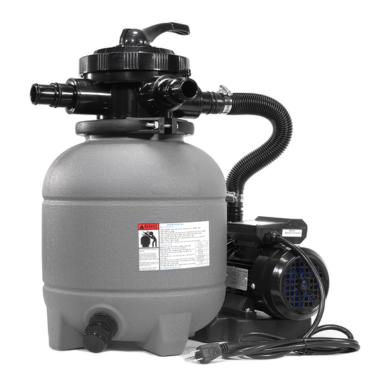
POOL SAND FILTER 12" W/ PUMP 2400GPH 6VALVE
ITEM #75030
OWNER'S MANUAL AND SAFETY INSTRUCTIONS
SAVE THIS MANUAL: KEEP THIS MANUAL FOR SAFETY WARNINGS, PRECAUTIONS, ASSEMBLY,
OPERATING, INSPECTION, MAINTENANCE AND CLEANING PROCEDURES. WRITE THE PRODUCT'S
SERIAL NUMBER ON THE BACK OF THE MANUAL NEAR THE ASSEMBLY DIAGRAM (OR MONTH
AND YEAR OF PURCHASE IF PRODUCT HAS NO NUMBER).
FOR QUESTIONS PLEASE CALL OUR CUSTOMER SUPPORT: (909) 628 0880 MON-FRI 9AM TO 3PM PST
Advertisement
Table of Contents

Related Manuals for XtremepowerUS 75030


Summary of Contents for XtremepowerUS 75030
- Page 1 POOL SAND FILTER 12" W/ PUMP 2400GPH 6VALVE ITEM #75030 OWNER’S MANUAL AND SAFETY INSTRUCTIONS SAVE THIS MANUAL: KEEP THIS MANUAL FOR SAFETY WARNINGS, PRECAUTIONS, ASSEMBLY, OPERATING, INSPECTION, MAINTENANCE AND CLEANING PROCEDURES. WRITE THE PRODUCT’S SERIAL NUMBER ON THE BACK OF THE MANUAL NEAR THE ASSEMBLY DIAGRAM (OR MONTH AND YEAR OF PURCHASE IF PRODUCT HAS NO NUMBER).
-
Page 2: Safety Information
SAFETY INFORMATION SAFETY INFORMATION 1. The sand filters are designed to work with water at temperature>than 0℃ and <than 45℃.The filter should never be operated outside of these temperatures or damage may occur. 2. The installation should be carried out in accordance to the safety instructions of swimming pools and the specific instructions for each facility. - Page 3 I N S T A L L A T I O N How to install the filter tank 1. Mount the Pump to sand filter support by using bolts and nuts. 2. Install the drain plug assembly to sand tank as below pictures. 3.
-
Page 4: Installation
INSTALLATION 4. Insert the tube with the diffuser body inside the tank as above picture, then place the funnel on the tank's mouth and pour the quartz sand into the tank (about23kg) 5. Take away the funnel, and then please make sure tank!s neck is very clean. Put the O-ring on the valve and use clamp to fix the valve with tank! (the direction of "PUMP# port on valve needs to face pump out port). -
Page 5: Installation Notes
INSTALLATION INSTALLATION NOTES: 1. Make sure the filter is worked under the work pressure, and using a pressure control valve when the system using a booster pump. 2. If the pump position is higher than the water level, it requires to install the back water control valve. 3. - Page 6 INSTALLATION FILTER CONTROL VALVE FUNCTIONS: FILTER - Set valve to FILTER for normal filtering. Also used for regular vacuuming. BACKWASH – For cleaning filter. When filter pressure gauge rises 8-10 PSI (0.55-0.69 BAR) above the initial start-up pressure. Stop the pump, set valve to BACKWASH. Start pump and backwash until water in sight glass is clear. Approximately 2 minutes or less depending on dirt accumulation.
-
Page 7: Parts Information
647201276000 Scre w M 6 X 25 an d Nut M6 for 75030 72712000 Adaptor with o-ring 47303205080 97208 H o se Clamp 1 1/4″ 32mm 35cm hose for 75030 5749017080 7-Way Valve 647304271000 47303005080 Flange clamp 647304272000 Filter Assembly... -
Page 8: Please Read The Following Carefully
PLEASE READ THE FOLLOWING CAREFULLY THE MANUFACTURER AND/OR DISTRIBUTOR HAS PROVIDED THE PARTS LIST AND ASSEMBLY DIAGRAM IN THIS MANUAL AS A REFERENCE TOOL ONLY. NEITHER THE MANUFACTURER OR DISTRIBUTOR MAKES ANY REPRESENTATION OR WARRANTY OF ANY KIND TO THE BUYER THAT HE OR SHE IS QUALIFIED TO MAKE ANY REPAIRS TO THE PRODUCT, OR THAT HE OR SHE IS QUALIFIED TO REPLACE ANY PARTS OF THE PRODUCT.
Need help?
Do you have a question about the 75030 and is the answer not in the manual?
Questions and answers
Why is there not much backwash water coming out during backwashing? Pool return is strong, pressure gauge reads About 8 which is normal. No obstruction in skimmer basket or pump basket.
There may not be much backwash water coming out during backwashing for XtremepowerUS part number 75030 due to one or more of the following reasons:
1. The filter is not dirty enough—backwashing is only needed when the pressure gauge reads 8–10 PSI (0.55–0.69 BAR) above the initial clean pressure.
2. The pump may not be running during backwash—backwashing requires the pump to be on after setting the valve to BACKWASH.
3. The pump strainer or skimmer baskets may be clogged—this can reduce water flow.
4. There could be a blockage or restriction in the hoses or plumbing—damaged or deformed hoses can reduce water flow.
Ensure the pump is running, the valve is set correctly, and the system is clean and free of blockages.
This answer is automatically generated
I broke the cover on the pressure gauge. Where can I get one