Table of Contents
Advertisement
Quick Links
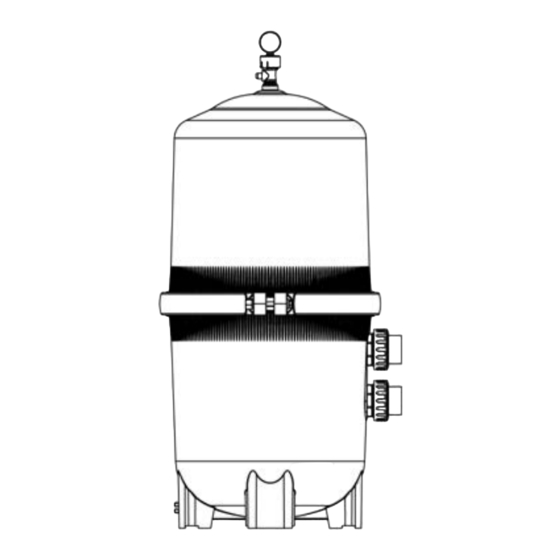
DE FILTER 62FT / 48FT
ITEM:75205 / 75206
DESIGN FLOWRATE
EFFECTIVE FILTRATION RATE
Residential
Commercial
MODEL
2
2
FT
M
GPM
LPM
7
4
120
75205
4 4
6
63
75206
MAXIMUM WORKING PRESSURE FOR ALL MODELS 50 PSI (3.45 BAR)
ATTENTION INSTALLER: THIS MANUAL CONTAINS IMPORTANT INFORMATION ON THE
OPERATION, AND SAFE USE OF THIS EQUIPMENT.
THIS MANUAL IS INTENDED FOR THE END USER OF THIS PRODUCT
Advertisement
Table of Contents

Related Manuals for XtremepowerUS 62FT


Summary of Contents for XtremepowerUS 62FT
- Page 1 DE FILTER 62FT / 48FT ITEM:75205 / 75206 DESIGN FLOWRATE EFFECTIVE FILTRATION RATE Residential Commercial MODEL 75205 75206 MAXIMUM WORKING PRESSURE FOR ALL MODELS 50 PSI (3.45 BAR) ATTENTION INSTALLER: THIS MANUAL CONTAINS IMPORTANT INFORMATION ON THE OPERATION, AND SAFE USE OF THIS EQUIPMENT.
- Page 2 This is the safety-alert symbol. When you see this symbol on your equipment or in this manual, look for one of the following signal words and be alert to the potential for personal injury or death. WARNING Warns about hazards that could cause serious personal injury or, death, and or major property damage and if ignored presents a potential hazard.
-
Page 3: Warning - Suction Entrapment Hazard
WARNING ELECTROCUTION HAZARD High Voltage electricity is present in the pool and spa equipment. High voltage electricity can cause shock and electrocution. Shock and electrocution can result in severe personal injury or death. National Electrical Code (NEC). bonding requirements. WARNING – SUCTION ENTRAPMENT HAZARD. Suction in suction outlets and/or suction outlet covers that are, damaged, broken, cracked, missing, or unsecured can cause severe injury and/or death due to the following entrapment hazards: Hair Entrapment- Hair can become entangled in suction outlet cover. -
Page 4: Installation
GENERAL INFORMATION Vertical Grid D.E. Filter combines superior water filtration with ease of operation and totally corrosion-free construction. It uses diatomaceous earth (D.E.), which is the most efficient dirt remover and filter medium known. The D.E., which is usually fed through the skimmer at initial start-up, uniformly coats the filter elements that are covered with a custom fitted monofilament polypropylene filter cloth. -
Page 5: Operation
STARTING THE PUMP and FILTER SYSTEM WARNING Before Starting the Pump 1. Use ONLY Original components; Non-Original clamp components may fail in use and cause explosive components. (See Fig 2) the pool. 4. Place the manual air relief valve in OPEN position. (See Fig 2) Starting Pump water leakage has stopped. - Page 6 FILTER CONTROL VALVE FUNCTIONS Six-Way Filter Control Valve FILTER – BACKWASH – O-RING a. Shut off the pump. RETAINER NUT b. Set Filter Control Valve to BACKWASH. c. Start Pump and backwash approximately two minutes, WASHER or until water out waste line appears clean. MANIFOLD d.
- Page 7 MAINTAINING YOUR FILTER WARNING This product should be installed and serviced only by FILTER DISASSEMBLY INSTRUCTIONS 1. Turn off all system circulation pumps and all electric power on the equipment pad. 3. The manual air relief valve must be placed in the OPEN position. (Fig 6) and the clamp bolt.
- Page 8 FILTER RE-ASSEMBLY INSTRUCTIONS WARNING RE-INSTALLING 1. Lubricate outlet elbow O-rings Replace filter element cluster into filter tank, carefully fitting top collector manifold outlet over outlet elbow O-ring. ALIGN LABELS CLEAN SEAL RING AND SEAL SURFACE DRAIN clean seal of all dirt and debris. (Fig 4) Do not use a solvent. PLUG LOWER FILTER...
- Page 9 REMOVING THE MANUAL AIR RELIEF VALVE WARNING This product should be installed and serviced only Your Filter comes with a Manual Air Relief Valve (MAR) preinstalled rom the factory. to be serviced, follow these instructions carefully. 1. Turn off all system circulation pumps and all electric power on the equipment pad.
-
Page 10: Service And Repairs
SERVICE AND REPAIRS SUGGESTED POOL CHEMISTRY LEVELS 7.2 to 7.8 TOTAL ALKALINITY 80 to 120 ppm CALCIUM HARDNESS 200 to 400 ppm COMBINED CHLORINE .2 ppm Maximum CHLORINE (STABILIZED) 1.0 to 3.0 ppm CHLORINE STABILIZER 60 to 80 ppm (Cyanuric Acid) PROBLEM SOLVING LIST LOW WATER FLOW SHORT FILTER CYCLES... - Page 11 Part No. Description 5024015000 Pressure Gauge 647311973000 Manual Air Relief Assembly 47311901080 Upper Filter Body(small) 47311905080 Upper Filter Body(large) 647311971000 Clamp System 5431146080 O-Ring 5758083000 Air Relief Filter 5431073080 O-Ring 47311913001 Adaptor 5748122001 PVC Pipe (short) 5748123001 PVC Pipe (long) 47311908001 Adaptor(short) 47311909001...
-
Page 12: Please Read The Following Carefully
OF NOTE PLEASE READ THE FOLLOWING CAREFULLY THE MANUFACTURER AND/OR DISTRIBUTOR HAS PROVIDED THE PARTS LIST AND ASSEMBLY DIAGRAM IN THIS MANUAL AS A REFERENCE TOOL ONLY. NEITHER THE MANUFACTURER OR DISTRIBUTOR MAKES ANY REPRESENTATION OR WARRANTY OF ANY KIND TO THE BUYER THAT HE OR SHE IS QUALIFIED TO MAKE ANY REPAIRS TO THE PRODUCT, OR THAT HE OR SHE IS QUALIFIED TO REPLACE ANY PARTS OF THE PRODUCT.
Need help?
Do you have a question about the 62FT and is the answer not in the manual?
Questions and answers