
Related Manuals for Canvas ROBSON 168-0048-0


Summary of Contents for Canvas ROBSON 168-0048-0
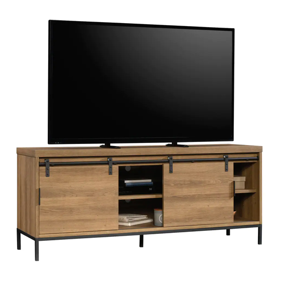
- Page 1 ROBSON MEDIA STAND MODEL NO. 168-0048-0 ASSEMBLY INSTRUCTIONS Toll free: 1-888-670-6684 IMPORTANT: Please read this manual carefully before beginning assembly of this product. Keep this manual for future reference.
- Page 2 MADE IN CHINA IMPORTED BY TRILEAF DISTRIBUTION TRIFEUIL TORONTO, CANADA M4S 2B8...
- Page 3 Important Safety Instructions Parts List Assembly Preparation Assembly 9-22 Cleaning and Maintenance Technical Data Warranty Warning! To reduce the risk of serious injury, read the following safety instructions before assembling and using the media stand. • Death or serious injury may occur when children climb on audio and/or video equipment furniture. A remote control or toys placed on the furniture may encourage a child to climb on the furniture and as a result may tip over onto the child.
- Page 4 MODEL NO. 168-0048-0 Right End - 1 Bottom - 1 Left End - 1 Valance - 1 Right Upright - 1 Back - 1 Large Shelf - 1 Left Upright - 1 Top - 1 Small Shelf - 2...
- Page 5 Right Door - 1 Short Brace - 1 Left Door - 1 Foot - 1 Leg - 2 Tube - 1 Long Brace - 2...
- Page 6 MODEL NO. 168-0048-0 Hidden Cam - 17 Pin with Sleeve - 8 Cam Screw - 17 Metal Pin - 4 Wood Dowel - 12 Pull - 2 Bracket - 4 Nail - 30 Retaining Bar - 4 Applique Card - 3 Door Bracket - 4 Bumper Card - 1...
- Page 7 WARNING • AVERTISSEMENT Never use this furniture with a Ne jamais utiliser ce meuble avec TV that is too large or too heavy. un téléviseur qui soit trop large ou Severe injury or death can occur. trop lourd. Risque de provoquer The TV and furniture will be des blessures graves, voire mor- unstable and may tip.
- Page 8 MODEL NO. 168-0048-0 CAUTION! • Proper placement of your media stand is essential. • Keep children away during assembly. This product contains small parts which can be swallowed by children. • Keep fi ngers away from the places where they can be pinched or trapped •...
- Page 9 Step 1 Requires A, B, C, D, F, G, 1 Push seventeen HIDDEN CAMS (1) into the ENDS (A and B), UPRIGHTS (C and D), BOTTOM (F), and VALANCE (G). Arrow (17 used) Arrow Hole The arrow in the HIDDEN CAM must point toward the hole in the edge of the board.
- Page 10 MODEL NO. 168-0048-0 Step 2 Requires A, B, E, 2 Turn seventeen CAM SCREWS (2) into the exact holes shown in the ENDS (A and B) and TOP (E). (17 used)
- Page 11 Step 3 Requires B, F, G, 3 Insert one WOOD DOWEL (3) into the LEFT END (B). Fasten the VALANCE (G) to the LEFT END (B). Tighten one HIDDEN CAM. NOTE: Ensure the WOOD DOWEL in the LEFT END has been inserted into the VALANCE (G). Insert one WOOD DOWEL (3) into the LEFT END (B).
- Page 12 MODEL NO. 168-0048-0 Step 4 Requires A, C, D, 3, 15 Insert two WOOD DOWELS (3) into the RIGHT END (A). Fasten the RIGHT END (A) to the BOTTOM (F) and VALANCE (G). Tighten two HIDDEN CAMS. NOTE: Ensure the WOOD DOWELS in the RIGHT END have been inserted into the BOTTOM and VALANCE.
- Page 13 Step 5 Requires E, 3 Insert six WOOD DOWELS (3) into the TOP (E). Fasten the TOP (E) to the ENDS (A and B), UPRIGHTS (C and D), and VALANCE (G). Tighten eleven HIDDEN CAMS. NOTE: Ensure the WOOD DOWELS in the TOP have been inserted into the ENDS, UPRIGHTS, and VALANCE.
- Page 14 MODEL NO. 168-0048-0 Step 6 Requires H, 10 Unfold the BACK (H) and lay it over your unit. Make equal margins along all four edges of the BACK (H). Push on opposite corners of your unit if needed to make it “square”. Fasten the BACK (H) to your unit using the NAILS (10).
- Page 15 Step 7 Requires N, O, P, Q, 14, 21 Fasten the SHORT BRACE (P) to the LONG BRACES (O). Tighten four BLACK 1/2” HEX HEAD SCREWS (21) using the L-WRENCH (14). Fasten the FOOT (Q) to the SHORT BRACE (P). Tighten two BLACK 1/2” HEX HEAD SCREWS (21) using the L-WRENCH (14).
- Page 16 MODEL NO. 168-0048-0 Step 8 Requires N, O, 16, 17 Carefully turn your unit onto its top. NOTE: Start each SCREW a few turns before completely tightening any of them. Fasten the LEGS (N) to the BOTTOM (F). Use four BLACK 1-9/16” WAFER HEAD SCREWS (16).
- Page 17 Step 9 Requires 4, 20 Carefully stand your unit upright. Fasten four BRACKETS (4) to the VALANCE (G). Use four BLACK 1/2” FLAT HEAD SCREWS (20). NOTE: Position the BRACKETS exactly as shown. (4 used)
- Page 18 MODEL NO. 168-0048-0 Step 10 Requires J, K, R, 7, 8, 22 Fasten the TUBE (R) to the BRACKETS (4). Use four BLACK 3/8” MACHINE SCREWS (22). NOTE: Start each SCREW a few turns before completely tightening any of them. Insert four METAL PINS (8) into the hole locations of your choice in the centre surfaces of the UPRIGHTS (C and D).
- Page 19 Step 11 Requires L, M, 5, 9, 19, 20 Fasten the RETAINING BARS (5) to the DOORS (L and M) exactly as shown. Use eight BLACK 1/2” PAN HEAD SCREWS (19). Fasten the PULLS (9) to the DOORS (L and M) exactly as shown. Use four BLACK 1/2” FLAT HEAD SCREWS (20).
- Page 20 MODEL NO. 168-0048-0 Step 12 Requires L, M, 6, 18 Place the RETAINING BARS on the DOORS (L and M) into the groove in the BOTTOM (F). Place the DOOR BRACKETS (6) onto the TUBE (R). Fasten the DOOR BRACKETS (6) to the DOORS (L and M). Use eight BLACK 9/16”...
- Page 21 Step 13 Requires 13 Apply the WARNING LABEL (13) to the TOP (E). You should be able to read the label when the TV is removed from the unit. When the TV is in place, it should hide the label. Peel off the backing and apply the label as shown in the diagram.
- Page 22 MODEL NO. 168-0048-0 Step 14 Requires 11, 12 IMPORTANT: The BUMPERS are used to reduce the risk of fi ngers being pinched when sliding the DOOR. Peel the BUMPERS from the BUMPER CARD (12) and stick the BUMPERS on the PULLS and on the upper and lower corners of the inner sides of the DOORS (L and M).
- Page 23 CAUTION! • Check all screws and nuts periodically for tightness, fastening them again as required. • This product is intended for domestic indoor use only • The product should be placed on a flat horizontal surface. • Arrange necessary manpower when assembling or moving the product. •...
-
Page 24: Year Limited Warranty
MODEL NO. 168-0048-0 1-YEAR LIMITED WARRANTY This CANVAS™ product carries a one (1) year warranty against defects in workmanship and materials. Trileaf Distribution agrees to replace the defective product free of charge within the stated warranty period, when returned by the original purchaser with proof of purchase. This... -
Page 25: Instructions D'assemblage
MEUBLE MULTIMÉDIA ROBSON N° DE MODÈLE : 168-0048-0 INSTRUCTIONS D’ASSEMBLAGE Sans frais : 1 888 670-6684 IMPORTANT : Veuillez lire attentivement le présent guide avant de commencer l’assemblage de cet article. Conservez ce guide à titre de référence. - Page 26 FABRIQUÉ EN CHINE IMPORTÉ PAR TRILEAF DISTRIBUTION TRIFEUIL TORONTO, CANADA M4S 2B8...
- Page 27 Consignes de sécurité importantes Liste des pièces 28-31 Préparation en vue de l’assemblage Assemblage 33-46 Nettoyage et entretien Caractéristiques techniques Garantie Avertissement! Pour réduire le risque de blessures graves, lisez les consignes de sécurité suivantes avant d’assembler et d’utiliser le meuble multimédia.
- Page 28 N° DE MODÈLE : 168-0048-0 Panneau latéral droit – 1 Panneau inférieur – 1 Panneau latéral gauche – 1 Traverse – 1 Montant droit – 1 Panneau arrière – 1 Grande tablette – 1 Montant gauche – 1 Panneau supérieur – 1 Petite tablette –...
- Page 29 Porte droite – 1 Renfort court – 1 Porte gauche – 1 Pied – 1 Renfort avec pieds – 2 Tube – 1 Renfort long – 2...
- Page 30 N° DE MODÈLE : 168-0048-0 Dispositif de blocage à came invisible – 17 Goupille avec manchon – 8 Vis de came – 17 Goupille métallique – 4 Goujon en bois – 12 Poignée – 2 Support en angle – 4 Clou –...
- Page 31 WARNING • AVERTISSEMENT Never use this furniture with a Ne jamais utiliser ce meuble avec TV that is too large or too heavy. un téléviseur qui soit trop large ou Severe injury or death can occur. trop lourd. Risque de provoquer The TV and furniture will be des blessures graves, voire mor- unstable and may tip.
- Page 32 N° DE MODÈLE : 168-0048-0 ATTENTION! • Il est essentiel d’installer le meuble de télévision à un endroit approprié. • Éloignez les enfants au moment de l’assemblage. Cet article contient de petites pièces que les enfants peuvent facilement avaler. • Évitez de mettre vos doigts là où ils pourraient se coincer ou être pincés. •...
- Page 33 Étape 1 Nécessite les pièces A, B, C, D, F, G et 1 Insérez 17 DISPOSITIFS DE BLOCAGE À CAME INVISIBLE (1) dans les PANNEAUX LATÉRAUX (A et B), les MONTANTS (C ET D), le PANNEAU DU BAS (F) et la TRAVERSE (G).
- Page 34 N° DE MODÈLE : 168-0048-0 Étape 2 Nécessite les pièces A, B, E et 2 Insérez 17 VIS DE CAME (2) dans les trous, comme indiqué dans l’illustration, des PANNEAUX LATÉRAUX (A et B) et du PANNEAU SUPÉRIEUR (E). (17 utilisés)
- Page 35 Étape 3 Nécessite les pièces B, F, G et 3 Insérez un GOUJON EN BOIS (3) dans le PANNEAU LATÉRAL GAUCHE (B). Fixez la TRAVERSE (G) au PANNEAU LATÉRAL GAUCHE (B). Serrez un DISPOSITIF DE BLOCAGE À CAME INVISIBLE. REMARQUE : Assurez-vous que le GOUJON EN BOIS du PANNEAU LATÉRAL GAUCHE est bien inséré...
- Page 36 N° DE MODÈLE : 168-0048-0 Étape 4 Nécessite les pièces A, C, D, 3 et 15 Insérez 2 GOUJONS EN BOIS (3) dans le PANNEAU LATÉRAL DROIT (A). Fixez le PANNEAU LATÉRAL DROIT (A) au PANNEAU INFÉRIEUR (F) et à la TRAVERSE (G).
- Page 37 Étape 5 Nécessite les pièces E et 3 Insérez 6 GOUJONS EN BOIS (3) dans le PANNEAU SUPÉRIEUR (E). Fixez le PANNEAU SUPÉRIEUR (E) aux PANNEAUX LATÉRAUX (A et B), aux MONTANTS (C et D), et à la TRAVERSE (G). Serrez 11 DISPOSITIFS DE BLOCAGE À CAME INVISIBLE.
- Page 38 N° DE MODÈLE : 168-0048-0 Étape 6 Nécessite les pièces H et 10 Dépliez le PANNEAU ARRIÈRE (H) et déposez-le sur le meuble. Alignez les bords du meuble avec ceux du PANNEAU ARRIÈRE (H). Poussez sur les coins opposés du meuble s’il est nécessaire de le rendre « droit ». Fixez le PANNEAU ARRIÈRE (H) au meuble avec des CLOUS (10).
- Page 39 Étape 7 Nécessite les pièces N, O, P, Q, 14 et 21 Fixez le RENFORT COURT (P) aux RENFORTS LONGS (O). Serrez 4 VIS À TÊTE HEXAGONALE NOIRES 1/2 PO (21) au moyen de la CLÉ COUDÉE (14). Fixez le PIED (Q) au RENFORT COURT (P). Serrez 2 VIS À TÊTE HEXAGONALE NOIRES 1/2 PO (21) au moyen de la CLÉ...
- Page 40 N° DE MODÈLE : 168-0048-0 Étape 8 Nécessite les pièces N, O, 16 et 17 Retournez soigneusement le meuble. REMARQUE : Tournez chaque VIS légèrement avant d’en serrer une au complet. Fixez les RENFORTS AVEC PIEDS (N) au PANNEAU INFÉRIEUR (F). Utilisez 4 VIS À TÊTE MINCE NOIRES 1 9/16 PO (16).
- Page 41 Étape 9 Nécessite les pièces 4 et 20 Soulevez soigneusement votre meuble à la verticale. Fixez 4 SUPPORTS EN ANGLE (4) à la TRAVERSE (G). Utilisez 4 VIS À TÊTE PLATE NOIRES 1/2 PO (20). REMARQUE : Placez les SUPPORTS EN ANGLE tel qu’illustré. (4 utilisées)
- Page 42 N° DE MODÈLE : 168-0048-0 Étape 10 Nécessite les pièces J, K, R, 7, 8 et 22 Fixez le TUBE (R) aux SUPPORTS EN ANGLE (4). Utilisez 4 VIS MÉCANIQUES NOIRES 3/8 PO (22). REMARQUE : Tournez chaque VIS légèrement avant d’en serrer une au complet. Insérez 4 GOUPILLES MÉTALLIQUES (8) dans les trous de votre choix dans les surfaces centrales des MONTANTS (C et D).
- Page 43 Étape 11 Nécessite les pièces L, M, 5, 9, 19 et 20 Fixez les BARRES D’ANCRAGE (5) aux PORTES (L et M) comme illustré. Utilisez 8 VIS À TÊTE CYLINDRIQUE BOMBÉE NOIRES 1/2 PO (19). Fixez les POIGNÉES (9) aux PORTES (L et M) comme illustré. Utilisez 4 VIS À TÊTE PLATE NOIRES 1/2 PO (20).
- Page 44 N° DE MODÈLE : 168-0048-0 Étape 12 Nécessite les pièces L, M, 6 et 18 Placez les BARRES D’ANCRAGE fi xées aux PORTES (L et M) dans la rainure du BAS (F). Placez les SUPPORTS DE PORTE (6) sur le TUBE (R). Fixez les SUPPORTS DE PORTE (6) aux PORTES (L et M).
- Page 45 Étape 13 Nécessite la pièce 13 Apposez l’ÉTIQUETTE D’AVERTISSEMENT (13) sur le PANNEAU SUPÉRIEUR (E). Vous devez être en mesure de lire l’étiquette lorsque le téléviseur n’est pas sur le meuble. Lorsque le téléviseur est en place, il devrait cacher l’étiquette. Retirez la pellicule de l’étiquette et collez-la comme indiqué...
- Page 46 N° DE MODÈLE : 168-0048-0 Étape 14 Nécessite les pièces 11 et 12 IMPORTANT: Les ARRÊTS DE PORTE servent à réduire le risque de se pincer les doigts en faisant glisser la PORTE. Enlevez les ARRÊTS DE PORTE de la CARTE D’ARRÊTS DE PORTE (12) et collez-les sur les POIGNÉES et les coins supérieurs et inférieurs des côtés intérieurs des PORTES (L et M).
- Page 47 ATTENTION! • Vérifi ez tous les écrous et les vis périodiquement pour voir s’ils sont bien serrés, et resserrez-les au besoin. • Cet article est conçu exclusivement pour un usage résidentiel à l’intérieur. • Cet article doit être placé sur un sol plat. •...
-
Page 48: Garantie Limitée De 1 An
N° DE MODÈLE : 168-0048-0 GARANTIE LIMITÉE DE 1 AN Cet article CANVAS comporte une garantie de un (1) an contre les défauts de fabrication et de matériau(x). Distribution Trifeuil consent à remplacer l’article défectueux sans frais lorsqu’il est retourné, accompagné de la preuve d’achat, par l’acquéreur initial au cours de la période de...
Need help?
Do you have a question about the ROBSON 168-0048-0 and is the answer not in the manual?
Questions and answers