
Related Manuals for Canvas ROBSON 168-0046-4


Summary of Contents for Canvas ROBSON 168-0046-4
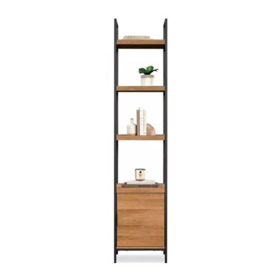
- Page 1 ROBSON NARROW BOOKCASE MODEL NO. 168-0046-4 ASSEMBLY INSTRUCTIONS Toll free: 1-888-670-6684 IMPORTANT: Please read this manual carefully before beginning assembly of this product. Keep this manual for future reference.
- Page 2 MADE IN CHINA IMPORTED BY TRILEAF DISTRIBUTION TRIFEUIL TORONTO, CANADA M4S 2B8...
- Page 3 Important Safety Instructions Parts List Assembly Preparation Assembly 8-34 Cleaning and Maintenance Technical Data Warranty Warning! To reduce the risk of serious injury, read the following safety instructions before assembling and using the bookcase. Death or serious injury may occur when children climb on storage or bookcase type furniture.
- Page 4 MODEL NO. 168-0046-4 MODEL NO. 168-0046-4 Top Shelf - 1 Cabinet End - 2 Upper Middle Shelf - 1 Cabinet Back - 1 Door - 1 Cabinet Top - 1 Upper Right End - 1 Cabinet Bottom - 1 Lower Right End - 1...
- Page 5 Hidden Cam - 6 Upper Left End - 1 Cam Screw - 6 Wood Dowel - 6 Applique Card - 1 Lower Left End - 1 Magnetic Catch - 1 Pivot Hinge Set - 1 Brace - 2 Strike Plate - 1 Lower Middle Shelf - 1 Pull - 1...
- Page 6 MODEL NO. 168-0046-4 MODEL NO. 168-0046-4 Bushing - 2 Black 5/8” Pan Head Screw - 2 L-Wrench - 1 Black 1/2” Machine Screw - 8 Black 1- 1/2” Flat Head Screw - 6 Black 1/2” Hex Head Screw - 4 Black 1-3/8”...
- Page 7 CAUTION! • Proper placement of your bookcase is essential. • Keep children away during assembly. This product contains small parts which can be swallowed by children. • Keep fi ngers away from the places where they can be pinched or trapped •...
- Page 8 MODEL NO. 168-0046-4 Step 1 Requires E, G, 1 Push six HIDDEN CAMS (1) into the CABINET ENDS (E) and CABINET BACK (G). Arrow (6 used) Arrow Hole The arrow in the HIDDEN CAM must point toward the hole in the edge of the board.
- Page 9 Step 2 Requires I, J, K, L, 15 Fasten the UPPER RIGHT END (I) to the LOWER RIGHT END (J). Use four BLACK 1/2” MACHINE SCREWS (15). Fasten the UPPER LEFT END (K) to the LOWER LEFT END (L). Use four BLACK 1/2” MACHINE SCREWS (15).
- Page 10 MODEL NO. 168-0046-4 Step 3 You have the option to assembly your unit with the door opening to the left or to the right. The two options are shown below. Follow step 4-15 for the right option and steps 16-27 for the left option. DOOR OPENING RIGHT DOOR OPENING LEFT...
- Page 11 Step 4 - Door opening right Requires C, 2, 3, 5, 9, 14 Turn six CAM SCREWS (2) into the exact holes shown in the CABINET TOP (C). Fasten the MAGNETIC CATCH (5) to the CABINET TOP (C). Use two BLACK 5/8” PAN HEAD SCREWS (14).
- Page 12 MODEL NO. 168-0046-4 Step 5 Requires C, G Fasten the CABINET TOP (C) to the CABINET BACK (G). Tighten two HIDDEN CAMS. NOTE: Ensure the WOOD DOWEL in the CABINET TOP has been inserted into the hole in the CABINET BACK. DOOR OPENING RIGHT Surface with HIDDEN CAMS...
- Page 13 Step 6 Requires E Fasten the CABINET ENDS (E) to the CABINET TOP (C). Tighten four HIDDEN CAMS. NOTE: Ensure the WOOD DOWELS in the CABINET TOP have been inserted into the holes in the CABINET ENDS. DOOR OPENING RIGHT Surface with HIDDEN CAMS Surface without...
- Page 14 MODEL NO. 168-0046-4 Step 7 REQUIRES D, 3, 11 Insert three WOOD DOWELS (3) into the CABINET ENDS (E) and CABINET BACK (G). Fasten the CABINET BOTTOM (D) to the CABINET ENDS (E) and CABINET BACK (G). Use six BLACK 1-1/2” FLAT HEAD SCREWS (11). NOTE: Ensure the WOOD DOWELS in the CABINET ENDS and CABINET BACK have been inserted into the holes in the CABINET BOTTOM.
- Page 15 Step 8 Requires K, L, 13 Fasten the LOWER LEFT END (L) to the CABINET BOTTOM (D). Use two BLACK 1-1/8” WAFER HEAD SCREWS (13). DOOR OPENING RIGHT...
- Page 16 MODEL NO. 168-0046-4 Step 9 Requires M, 10, 13, 16 Fasten the BRACES (M) to the LOWER LEFT END (L). Turn two BLACK 1/2” HEX HEAD SCREWS (16) with the L-WRENCH (10). Fasten the BRACES (M) to the CABINET BOTTOM (D). Use four BLACK 1-1/8” WAFER HEAD SCREWS (13).
- Page 17 Step 10 Requires A, B, N, 12, 98 Open the FURNITURE TIPPING RESTRAINT KIT (98) and fasten the SAFETY STRAP to the TOP SHELF (A). Use the short screw through the hole in the strap and into the top surface of the TOP SHELF (A).
- Page 18 MODEL NO. 168-0046-4 Step 11 Requires I, J, 10, 12, 13, 16 Fasten the LOWER RIGHT END (J) to the BRACES (M). Turn two BLACK 1/2” HEX HEAD SCREWS (16) with the L-WRENCH (10). Fasten the LOWER RIGHT END (J) to the CABINET BOTTOM (D). Use two BLACK 1-1/8” WAFER HEAD SCREWS (13).
- Page 19 Step 12 Requires H, 6, 7, 8, 17, 18 Fasten a PIVOT HINGE (6) to the DOOR (H). Use two BLACK 1/2” PAN HEAD SCREWS (17). Fasten the STRIKE PLATE (7) to the DOOR (H). Use a BLACK 1/2” FLAT HEAD SCREW (18). Fasten the PULL (8) to the DOOR (H).
- Page 20 MODEL NO. 168-0046-4 Step 13 Requires H, 6, 9, 17 Carefully stand your unit upright. 1. Push a BUSHING (9) into the hole in the CABINET BOTTOM (D). Then, insert a PIVOT HINGE (6) into the BUSHING. 2. Insert the PIVOT HINGE, which is fastened to the DOOR (H), into the hole in the CABINET TOP (C).
- Page 21 Step 14 Requires 98 Use the FURNITURE TIPPING RESTRAINT KIT (98) for added stability. Place your unit in its fi nal location against a wall. Locate the centre of a stud in your wall near your unit and mark it with a pencil. Next, drill a 1/8” hole on the mark and into the stud in your wall.
-
Page 22: Hidden Cam
MODEL NO. 168-0046-4 Step 15 Requires 4 Peel APPLIQUES from the APPLIQUE CARD (4) and stick them onto each visible HIDDEN CAM. This completes assembly. DOOR OPENING RIGHT 15 lbs. (6.8 kg) 25 lbs. (11.3 kg) 25 lbs. (11.3 kg) 25 lbs. - Page 23 Step 16 - Door opening left Requires C, 2, 3, 5, 9, 14 Turn six CAM SCREWS (2) into the exact holes shown in the CABINET TOP (C). Fasten the MAGNETIC CATCH (5) to the CABINET TOP (C). Use two BLACK 5/8” PAN HEAD SCREWS (14).
- Page 24 MODEL NO. 168-0046-4 Step 17 Requires C, G Fasten the CABINET TOP (C) to the CABINET BACK (G). Tighten two HIDDEN CAMS. NOTE: Ensure the WOOD DOWEL in the CABINET TOP has been inserted into the hole in the CABINET BACK. DOOR OPENING LEFT ...
- Page 25 Step 18 Requires E Fasten the CABINET ENDS (E) to the CABINET TOP (C). Tighten four HIDDEN CAMS. NOTE: Ensure the WOOD DOWELS in the CABINET TOP have been inserted into the holes in the CABINET ENDS. DOOR OPENING LEFT Surface with HIDDEN CAMS Surface without...
- Page 26 MODEL NO. 168-0046-4 Step 19 REQUIRES D, 3, 11 Insert three WOOD DOWELS (3) into the CABINET ENDS (E) and CABINET BACK (G). Fasten the CABINET BOTTOM (D) to the CABINET ENDS (E) and CABINET BACK (G). Use six BLACK 1-1/2” FLAT HEAD SCREWS (11). NOTE: Ensure the WOOD DOWELS in the CABINET ENDS and CABINET BACK have been inserted into the holes in the CABINET BOTTOM.
- Page 27 Step 20 Requires K, L, 13 Fasten the LOWER LEFT END (L) to the CABINET BOTTOM (D). Use two BLACK 1-1/8” WAFER HEAD SCREWS (13). DOOR OPENING LEFT ...
- Page 28 MODEL NO. 168-0046-4 Step 21 Requires M, 10, 13, 16 Fasten the BRACES (M) to the LOWER LEFT END (L). Turn two BLACK 1/2” HEX HEAD SCREWS (16) with the L-WRENCH (10). Fasten the BRACES (M) to the CABINET BOTTOM (D). Use four BLACK 1-1/8” WAFER HEAD SCREWS (13).
- Page 29 Step 22 Requires A, B, N, 12, 98 Open the FURNITURE TIPPING RESTRAINT KIT (98) and fasten the SAFETY STRAP to the TOP SHELF (A). Use the short screw through the hole in the strap and into the top surface of the TOP SHELF (A).
- Page 30 MODEL NO. 168-0046-4 Step 23 Requires I, J, 10, 12, 13, 16 Fasten the LOWER RIGHT END (J) to the BRACES (M). Turn two BLACK 1/2” HEX HEAD SCREWS (16) with the L-WRENCH (10). Fasten the LOWER RIGHT END (J) to the CABINET BOTTOM (D). Use two BLACK 1-1/8” WAFER HEAD SCREWS (13).
- Page 31 Step 24 Requires H, 6, 7, 8, 17, 18 Fasten a PIVOT HINGE (6) to the DOOR (H). Use two BLACK 1/2” PAN HEAD SCREWS (17). Fasten the STRIKE PLATE (7) to the DOOR (H). Use a BLACK 1/2” FLAT HEAD SCREW (18). Fasten the PULL (8) to the DOOR (H).
- Page 32 MODEL NO. 168-0046-4 Step 25 Requires H, 6, 9, 17 Carefully stand your unit upright. 1. Push a BUSHING (9) into the hole in the CABINET BOTTOM (D). Then, insert a PIVOT HINGE (6) into the BUSHING. 2. Insert the PIVOT HINGE, which is fastened to the DOOR (H), into the hole in the CABINET TOP (C).
- Page 33 Step 26 Requires 98 Use the FURNITURE TIPPING RESTRAINT KIT (98) for added stability. Place your unit in its fi nal location against a wall. Locate the centre of a stud in your wall near your unit and mark it with a pencil. Next, drill a 1/8” hole on the mark and into the stud in your wall.
- Page 34 MODEL NO. 168-0046-4 Step 27 Requires 4 Peel APPLIQUES from the APPLIQUE CARD (4) and stick them onto each visible HIDDEN CAM. This completes assembly. DOOR OPENING LEFT 15 lbs. (6.8 kg) 25 lbs. (11.3 kg) 25 lbs. (11.3 kg) 25 lbs.
- Page 35 CAUTION! • Check all screws and nuts periodically for tightness, fastening them again as required. • This product is intended for domestic indoor use only • The product should be placed on a flat horizontal surface. • Arrange necessary manpower when assembling or moving the product. •...
-
Page 36: Year Limited Warranty
MODEL NO. 168-0046-4 1-YEAR LIMITED WARRANTY This CANVAS™ product carries a one (1) year warranty against defects in workmanship and materials. Trileaf Distribution agrees to replace the defective product free of charge within the stated warranty period, when returned by the original purchaser with proof of purchase. This... -
Page 37: Instructions D'assemblage
BIBLIOTHÈQUE ÉTROITE ROBSON NO DE MODÈLE 168-0046-4 INSTRUCTIONS D’ASSEMBLAGE Sans frais : 1 888 670-6684 IMPORTANT : Veuillez lire attentivement le présent guide avant de commencer l’assemblage de cet article. Conservez ce guide à titre de référence. - Page 38 FABRIQUÉ EN CHINE IMPORTÉ PAR TRILEAF DISTRIBUTION TRIFEUIL TORONTO, CANADA M4S 2B8...
- Page 39 Consignes de sécurité importantes Liste des pièces Préparation en vue de l’assemblage Assemblage 44-70 Nettoyage et entretien Caractéristiques techniques Garantie` Avertissement! Pour réduire le risque de blessures graves, lisez les consignes de sécurité suivantes avant d’assembler et d’utiliser la bibliothèque. Un accident entraînant des blessures graves ou mortelles peut survenir lorsqu’un enfant grimpe sur un meuble de type bibliothèque ou de rangement.
- Page 40 NO DE MODÈLE 168-0046-4 Tablette du haut – 1 Panneau latéral de l’armoire – 2 Tablette du milieu supérieure – 1 Panneau arrière de l’armoire – 1 Porte – 1 Panneau supérieur de l’armoire – 1 Cadre supérieur droit – 1 Panneau inférieur de l’armoire –...
- Page 41 Dispositif de blocage à came invisible – 6 Cadre supérieur gauche – 1 Vis de came – 6 Goujon en bois – 6 Carte d’autocollants – 1 Cadre inférieur gauche – 1 Fermeture magnétique – 1 Ensemble de charnières à pivot – 1 Renfort –...
- Page 42 NO DE MODÈLE 168-0046-4 Douille – 2 Vis à tête cylindrique bombée noire 5/8 po – 2 Clé coudée – 1 Vis mécanique noire 1/2 po – 8 Vis à tête plate noire 1 1/2 po – 6 Vis à tête hexagonale noire 1/2 po – 4 Vis à...
- Page 43 ATTENTION!! • Il est essentiel d’installer la bibliothèque à un endroit approprié. • Tenez les enfants à l’écart durant l’assemblage • Cet article contient de petites pièces que les enfants peuvent facilement avaler. • Évitez de mettre vos doigts là où ils pourraient se coincer ou être pincés. •...
- Page 44 NO DE MODÈLE 168-0046-4 Étape 1 Nécessite les pièces E, G et 1 Insérez les 6 DISPOSITIFS DE BLOCAGE À CAME INVISIBLE (1) dans les PANNEAUX LATÉRAUX DE L’ARMOIRE (E) et le PANNEAU ARRIÈRE DE L’ARMOIRE (G). Flèche (6 utilisés) Flèche Trou La fl...
- Page 45 Étape 2 Nécessite les pièces I, J, K, L et 15 Fixez le CADRE SUPÉRIEUR DROIT (L) au CADRE INFÉRIEUR DROIT (J). Utilisez 4 VIS MÉCANIQUES NOIRES 1/2 PO (15). Fixez le CADRE SUPÉRIEUR GAUCHE (K) au CADRE INFÉRIEUR GAUCHE (L). Utilisez 4 VIS MÉCANIQUES NOIRES 1/2 PO (15).
- Page 46 NO DE MODÈLE 168-0046-4 Étape 3 Vous avez la possibilité d’assembler votre meuble avec la porte s’ouvrant vers la gauche ou vers la droite. Les deux options sont illustrées ci-dessous. Suivez les étapes 4 à 15 pour une ouverture vers la droite et les étapes 16 à 27 pour une ouverture vers la gauche. OUVERTURE DE PORTE VERS LA DROITE OUVERTURE DE PORTE VERS LA GAUCHE...
- Page 47 Étape 4 – Ouverture de porte vers la droite Nécessite les pièces C, 2, 3, 5, 9 et 14 Insérez 6 VIS À CAME (2) dans les trous, comme indiqué dans l’illustration du PANNEAU SUPÉRIEUR DE L’ARMOIRE (C). Fixez la FERMETURE MAGNÉTIQUE (5) au PANNEAU SUPÉRIEUR DE L’ARMOIRE (C). Utilisez 2 VIS À...
- Page 48 NO DE MODÈLE 168-0046-4 Étape 5 Nécessite les pièces C et G Fixez le PANNEAU SUPÉRIEUR DE L’ARMOIRE (G) au PANNEAU ARRIÈRE DE L’ARMOIRE (G). Serrez les 2 DISPOSITIFS DE BLOCAGE À CAME INVISIBLE. REMARQUE : Assurez-vous que les GOUJONS EN BOIS du PANNEAU SUPÉRIEUR DE L’ARMOIRE sont bien insérés dans les trous du PANNEAU ARRIÈRE DE L’ARMOIRE.
- Page 49 Étape 6 Nécessite la pièce E Fixez les PANNEAUX LATÉRAUX DE L’ARMOIRE (E) au PANNEAU SUPÉRIEUR DE L’ARMOIRE (C). Serrez les 4 DISPOSITIFS DE BLOCAGE À CAME INVISIBLE. REMARQUE : Assurez-vous que les GOUJONS EN BOIS du PANNEAU SUPÉRIEUR DE L’ARMOIRE sont bien insérés dans les trous des PANNEAUX LATÉRAUX DE L’ARMOIRE.
- Page 50 NO DE MODÈLE 168-0046-4 Étape 7 Nécessite les pièces D, 3 et 11 Insérez 3 GOUJONS EN BOIS (3) dans les PANNEAUX LATÉRAUX (E) et le PANNEAU ARRIÈRE DE L’ARMOIRE (G). Fixez le PANNEAU INFÉRIEUR DE L’ARMOIRE (D) aux PANNEAUX LATÉRAUX DE L’ARMOIRE (E) et le PANNEAU ARRIÈRE DE L’ARMOIRE (G).
- Page 51 Étape 8 Nécessite les pièces K, L et 13 Fixez le CADRE INFÉRIEUR GAUCHE (L) au PANNEAU INFÉRIEUR DE L’ARMOIRE (D). Utilisez 2 VIS À TÊTE MINCE NOIRES 1 1/8 PO (13). OUVERTURE DE PORTE VERS LA DROITE...
- Page 52 NO DE MODÈLE 168-0046-4 Étape 9 Nécessite les pièces M, 10, 13 et 16 Fixez les RENFORTS (M) au CADRE INFÉRIEUR GAUCHE (L). Serrez 2 VIS À TÊTE HEXAGONALE NOIRES 1/2 PO (16) au moyen de la CLÉ COUDÉE (10). Fixez les RENFORTS (M) au PANNEAU INFÉRIEUR DE L’ARMOIRE (D).
- Page 53 Étape 10 Nécessite les pièces A, B, N, 12 et 98 Ouvrez la TROUSSE ANTI-BASCULEMENT POUR MEUBLES (98) et fi xez la SANGLE DE SÉCURITÉ à la TABLETTE DU HAUT (A). Insérez la vis de courte dans le trou de la sangle et le dessus de la TABLETTE DU HAUT (A).
- Page 54 NO DE MODÈLE 168-0046-4 Étape 11 Nécessite les pièces I, J, 10, 12, 13 et 16 Fixez le CADRE INFÉRIEUR DROIT (J) aux RENFORTS (M). Serrez 2 VIS À TÊTE HEXAGONALE NOIRES 1/2 PO (16) au moyen de la CLÉ COUDÉE (10). Fixez le CADRE INFÉRIEUR DROIT (J) au PANNEAU INFÉRIEUR DE L’ARMOIRE (D).
- Page 55 Étape 12 Nécessite les pièces H, 6, 7, 8, 17 et 18 Fixez 1 CHARNIÈRE À PIVOT (6) à la PORTE (H). Utilisez 2 VIS À TÊTE CYLINDRIQUE BOMBÉE NOIRES 1/2 PO (17). Fixez la GÂCHE (7) à la PORTE (H). Utilisez 1 VIS À TÊTE PLATE NOIRE 1/2 PO (18). Fixez la POIGNÉE (8) à...
- Page 56 NO DE MODÈLE 168-0046-4 Étape 13 Nécessite les pièces H, 6, 9 et 17 Carefully stand your unit upright. 1. Enfoncez 1 DOUILLE (9) dans le trou du PANNEAU INFÉRIEUR DE L’ARMOIRE (D). Ensuite, insérez 1 CHARNIÈRE À PIVOT (6) dans la DOUILLE. 2.
- Page 57 Étape 14 Nécessite la pièce 98 Utilisez la TROUSSE ANTI-BASCULEMENT POUR MEUBLES (98) pour plus de stabilité. Placez votre meuble à son emplacement fi nal contre un mur. Repérez le centre d’un montant mural près de votre meuble et marquez son emplacement avec un crayon. Ensuite, percez un trou de 1/8 po sur la marque du montant mural.
- Page 58 NO DE MODÈLE 168-0046-4 Étape 15 Nécessite la pièce 4 Apposez des AUTOCOLLANTS de la CARTE D’AUTOCOLLANTS (4) sur les DISPOSITIFS DE BLOCAGE À CAME INVISIBLE. Cela termine l’assemblage. OUVERTURE DE PORTE VERS LA DROITE 15 lb (6,8 kg) 25 lb (11,3 kg) 25 lb (11,3 kg)
- Page 59 Étape 16 – Ouverture de porte vers la gauche Nécessite les pièces C, 2, 3, 5, 9 et 14 Insérez 6 VIS À CAME (2) dans les trous, comme indiqué dans l’illustration du PANNEAU SUPÉRIEUR DE L’ARMOIRE (C). Fixez la FERMETURE MAGNÉTIQUE (5) au PANNEAU SUPÉRIEUR DE L’ARMOIRE (C). Utilisez 2 VIS À...
- Page 60 NO DE MODÈLE 168-0046-4 Étape 17 Nécessite les pièces C et G Fixez le PANNEAU SUPÉRIEUR DE L’ARMOIRE (G) au PANNEAU ARRIÈRE DE L’ARMOIRE (G). Serrez les 2 DISPOSITIFS DE BLOCAGE À CAME INVISIBLE. REMARQUE : Assurez-vous que les GOUJONS EN BOIS du PANNEAU SUPÉRIEUR DE L’ARMOIRE sont bien insérés dans les trous du PANNEAU ARRIÈRE DE L’ARMOIRE.
- Page 61 Étape 18 Nécessite la pièce E Fixez les PANNEAUX LATÉRAUX DE L’ARMOIRE (E) au PANNEAU SUPÉRIEUR DE L’ARMOIRE (C). Serrez les 4 DISPOSITIFS DE BLOCAGE À CAME INVISIBLE. REMARQUE : Assurez-vous que les GOUJONS EN BOIS du PANNEAU SUPÉRIEUR DE L’ARMOIRE sont bien insérés dans les trous des PANNEAUX LATÉRAUX DE L’ARMOIRE.
- Page 62 NO DE MODÈLE 168-0046-4 Étape 19 Nécessite les pièces D, 3 et 11 Insérez 3 GOUJONS EN BOIS (3) dans les PANNEAUX LATÉRAUX (E) et le PANNEAU ARRIÈRE DE L’ARMOIRE (G). Fixez le PANNEAU INFÉRIEUR DE L’ARMOIRE (D) aux PANNEAUX LATÉRAUX DE L’ARMOIRE (E) et le PANNEAU ARRIÈRE DE L’ARMOIRE (G).
- Page 63 Étape 20 Nécessite les pièces K, L et 13 Fixez le CADRE INFÉRIEUR GAUCHE (L) au PANNEAU INFÉRIEUR DE L’ARMOIRE (D). Utilisez 2 VIS À TÊTE MINCE NOIRES 1 1/8 PO (13). OUVERTURE DE PORTE VERS LA GAUCHE...
- Page 64 NO DE MODÈLE 168-0046-4 Étape 21 Nécessite les pièces M, 10, 13 et 16 Fixez les RENFORTS (M) au CADRE INFÉRIEUR GAUCHE (L). Serrez 2 VIS À TÊTE HEXAGONALE NOIRES 1/2 PO (16) au moyen de la CLÉ COUDÉE (10). Fixez les RENFORTS (M) au PANNEAU INFÉRIEUR DE L’ARMOIRE (D).
- Page 65 Étape 22 Nécessite les pièces A, B, N, 12 et 98 Ouvrez la TROUSSE ANTI-BASCULEMENT POUR MEUBLES (98) et fi xez la SANGLE DE SÉCURITÉ à la TABLETTE DU HAUT (A). Insérez la vis de courte dans le trou de la sangle et le dessus de la TABLETTE DU HAUT (A).
- Page 66 NO DE MODÈLE 168-0046-4 Étape 23 Nécessite les pièces I, J, 10, 12, 13 et 16 Fixez le CADRE INFÉRIEUR DROIT (J) aux RENFORTS (M). Serrez 2 VIS À TÊTE HEXAGONALE NOIRES 1/2 PO (16) au moyen de la CLÉ COUDÉE (10). Fixez le CADRE INFÉRIEUR DROIT (J) au PANNEAU INFÉRIEUR DE L’ARMOIRE (D).
- Page 67 Étape 24 Nécessite les pièces H, 6, 7, 8, 17 et 18 Fixez 1 CHARNIÈRE À PIVOT (6) à la PORTE (H). Utilisez 2 VIS À TÊTE CYLINDRIQUE BOMBÉE NOIRES 1/2 PO (17). Fixez la GÂCHE (7) à la PORTE (H). Utilisez 1 VIS À TÊTE PLATE NOIRE 1/2 PO (18). Fixez la POIGNÉE (8) à...
- Page 68 NO DE MODÈLE 168-0046-4 Étape 25 Nécessite les pièces H, 6, 9 et 17 Soulevez soigneusement votre meuble à la verticale. 1. Enfoncez 1 DOUILLE (9) dans le trou du PANNEAU INFÉRIEUR DE L’ARMOIRE (D). Ensuite, insérez 1 CHARNIÈRE À PIVOT (6) dans la DOUILLE. 2.
- Page 69 Étape 26 Nécessite la pièce 98 Utilisez la TROUSSE ANTI-BASCULEMENT POUR MEUBLES (98) pour plus de stabilité. Placez votre meuble à son emplacement fi nal contre un mur. Repérez le centre d’un montant mural près de votre meuble et marquez son emplacement avec un crayon. Ensuite, percez un trou de 1/8 po sur la marque du montant mural.
- Page 70 NO DE MODÈLE 168-0046-4 Étape 27 Nécessite la pièce 4 Apposez des AUTOCOLLANTS de la CARTE D’AUTOCOLLANTS (4) sur les DISPOSITIFS DE BLOCAGE À CAME INVISIBLE. Cela termine l’assemblage. OUVERTURE DE PORTE VERS LA GAUCHE 15 lb (6,8 kg) 25 lb (11,3 kg) 25 lb (11,3 kg)
- Page 71 ATTENTION! • Vérifi ez tous les écrous et les vis périodiquement pour voir s’ils sont bien serrés, et resserrez-les au besoin. • Cet article est conçu exclusivement pour un usage résidentiel à l’intérieur. • Cet article doit être placé sur un sol plat. •...
-
Page 72: Garantie Limitée De 1 An
NO DE MODÈLE 168-0046-4 GARANTIE LIMITÉE DE 1 AN Cet article CANVAS est couvert par une garantie d’un (1) an contre les défauts de matériaux et de fabrication. Distribution Trifeuil consent à remplacer l’article défectueux sans frais lorsqu’il est retourné, accompagné de la preuve d’achat, par l’acquéreur initial au cours de la période de garantie convenue.
Need help?
Do you have a question about the ROBSON 168-0046-4 and is the answer not in the manual?
Questions and answers