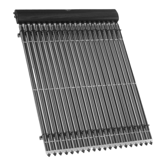
Viessmann VITOSOL 300-T Installation Instructions Manual
Vacuum tube collector based on the heat pipe principle
Hide thumbs
Also See for VITOSOL 300-T:
- Installation instructions manual (36 pages) ,
- Installation instructions for contractors (28 pages) ,
- Technical manual (144 pages)


Need help?
Do you have a question about the VITOSOL 300-T and is the answer not in the manual?
Questions and answers